background image

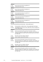
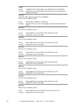
dSP | Axx

Fault in the central control and regulation unit
Contact After-Sales Service

Cause:
Remedy:

dSP | Cxx

Fault in the central control and regulation unit
Contact After-Sales Service

Cause:
Remedy:

dSP | Exx

Fault in the central control and regulation unit
Contact After-Sales Service

Cause:
Remedy:

dSP | Sy

Fault in the central control and regulation unit
Contact After-Sales Service

Cause:
Remedy:

dSP | nSy

Fault in the central control and regulation unit
Contact After-Sales Service

Cause:
Remedy:

E-S | toP

only with the External stop and External stop - inching enabled options

The External stop or External stop - inching enabled option has tripped
Acknowledge the service code via the robot control unit and re-apply the 24
V SELV safety voltage

Cause:
Remedy:

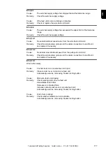
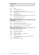
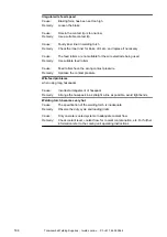
EFd | xx.x

Fault in the wire feed system (overcurrent in wire-feed unit drive)
Arrange the hosepack in as straight a line as possible; check that there are
no kinks or dirt in the inner liner; check the contact pressure on the 2-roller
(or 4-roller) drive

Wire-feed unit motor is sticking or defective
Check or replace the wire-feed unit motor

Cause:
Remedy:

Cause:
Remedy:

EFd | 8.1

Fault in the wire feed system (overcurrent in wire-feed unit drive)
Arrange the hosepack in as straight a line as possible; check that there are
no kinks or dirt in the inner liner; check the contact pressure on the 2-roller
(or 4-roller) drive

Wire-feed unit motor is sticking or defective
Check or replace the wire-feed unit motor

Cause:
Remedy:

Cause:
Remedy:

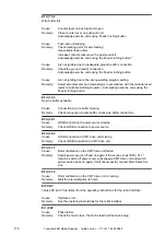
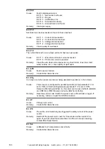
EFd | 8.2

Fault in the wire feed system (overcurrent in wire-feed unit drive)
Arrange the hosepack in as straight a line as possible; check that there are
no kinks or dirt in the inner liner; check the contact pressure on the 2-roller
(or 4-roller) drive

Cause:
Remedy:

176

Toowoomba Welding Supplies  :  tweld.com.au  :  Ph +61 7 4659 0044

Summary of Contents for CMT 4000 Advanced

Page 1: ...ified sustainable forests FSC Perfect Charging Perfect Welding Solar Energy TransSynergic 4000 5000 TransPuls Synergic 2700 TransPuls Synergic 3200 4000 5000 TIME 5000 Digital CMT 4000 Advanced EN Ope...

Page 2: ...Toowoomba Welding Supplies tweld com au Ph 61 7 4659 0044...

Page 3: ...stallation location and during transport 17 Safety measures in normal operation 17 Commissioning maintenance and repair 18 Safety inspection 18 Disposal 19 Safety symbols 19 Data protection 19 Copyrig...

Page 4: ...ombinations special functions 57 Displaying the feeder inching speed 57 Displaying the gas pre flow and gas post flow time 57 Displaying the software version 58 Yard control panel 59 Yard control pane...

Page 5: ...0 Digital 89 General 89 Fitting the system components overview 89 Fixing the strain relief device in place 90 Connecting the interconnecting hosepack 90 Connecting the gas cylinder 91 Establishing a g...

Page 6: ...rt Stop option 118 TIG welding with TIG Comfort Stop 119 MMA welding 121 Safety 121 Prerequisite 121 Preparation 121 Manual metal arc welding 122 Corrections during welding 122 Adjusting parameters fo...

Page 7: ...CMT control panels 153 Parameters for MIG MAG welding in the Setup menu level 2 153 Parameters for operating power sources in parallel in the Setup menu level 2 156 Parameters for TimeTwin Digital in...

Page 8: ...TIME 5000 Digital 200 CMT 4000 Advanced 201 CMT 4000 Advanced MV 202 Welding program databases 204 Explanation of symbols 204 Setting up a welding program database example 204 Terms and abbreviations...

Page 9: ...commissioning operating maintaining and servicing the device must be suitably qualified have sufficient knowledge of welding and read and follow these operating instructions carefully The operating i...

Page 10: ...31 F Relative humidity up to 50 at 40 C 104 F up to 90 at 20 C 68 F The surrounding air must be free from dust acids corrosive gases or substances etc Can be used at altitudes of up to 2000 m 6561 ft...

Page 11: ...isor and regulation filter Wear regulation protective goggles with side protection behind the protective visor Wear stout footwear that provides insulation even in wet conditions Protect the hands wit...

Page 12: ...d components should therefore be studied carefully Recommendations for trade fair scenarios risk management measures and for identify ing working conditions can be found on the European Welding Associ...

Page 13: ...wer source is switched on Double the open circuit voltage of a power source can occur between the welding elec trodes of two power sources Touching the potentials of both electrodes at the same time m...

Page 14: ...idential and industrial areas This is also true for residential areas in which the energy is supplied from the public low voltage mains EMC device classification as per the rating plate or technical d...

Page 15: ...injury piercing of the hand injuries to the face and eyes etc Therefore always keep the welding torch away from the body devices with wire feed unit and wear suitable protective goggles Never touch th...

Page 16: ...t and reduce welding quality Meet the following requirements regarding shielding gas quality Solid particle size 40 m Pressure condensation point 20 C Max oil content 25 mg m Use filters if necessary...

Page 17: ...y set up and operate the device in accordance with the degree of protection shown on the rating plate When setting up the device ensure there is an all round clearance of 0 5 m 1 ft 7 69 in to ensure...

Page 18: ...ebsite Check the coolant level before starting to weld while the system is still cool Commissioning maintenance and repair It is impossible to guarantee that bought in parts are designed and manufactu...

Page 19: ...elevant product standards of the EN 60 974 series Fronius International GmbH hereby declares that the device is compliant with Directive 2014 53 EU The full text on the EU Declaration of Conformity ca...

Page 20: ...20 Toowoomba Welding Supplies tweld com au Ph 61 7 4659 0044...

Page 21: ...General information 21 Toowoomba Welding Supplies tweld com au Ph 61 7 4659 0044...

Page 22: ...22 Toowoomba Welding Supplies tweld com au Ph 61 7 4659 0044...

Page 23: ...the power sources is coupled with a digital sig nal processor The central control and regulation unit and the signal processor control the entire welding process During the welding process the actual...

Page 24: ...sources come with extra warning notices affixed to the unit The warning notices must NOT be removed or painted over Nur vorhanden bei Stromquelle TPS 2700 und auf Drahtvorsch ben 24 Toowoomba Welding...

Page 25: ...l objects away 1 Electric shock can kill 1 1 Wear dry insulating gloves Do not touch electrode with bare hand Do not wear wet or damaged gloves 1 2 Protect yourself from electric shock by insulating y...

Page 26: ...tainers 4 Arc rays can burn eyes and injure skin 4 1 Wear hat and safety glasses Use ear protection and button shirt collar Use welding helmet with correct shade of filter Wear complete body protectio...

Page 27: ...se option CrNi edition The CrNi edition power sources were developed for perfect and careful processing of CrNi Special CrNi welding programs assist in the professional processing of high grade steels...

Page 28: ...owing features bring about faster welding speeds with an increase in deposition rate of up to 30 Power module with high voltage reserves High performance welding programs Specially selected shielding...

Page 29: ...in which the power source is to be used Overview 1 2 3 4 5 6 7 11 10 9 8 FR ON IU S Overview of system components Legend 1 Human hosepack boom 2 Remote controls 3 Welding torches 4 Wire feed units 5...

Page 30: ...30 Toowoomba Welding Supplies tweld com au Ph 61 7 4659 0044...

Page 31: ...Control elements and connections 31 Toowoomba Welding Supplies tweld com au Ph 61 7 4659 0044...

Page 32: ...32 Toowoomba Welding Supplies tweld com au Ph 61 7 4659 0044...

Page 33: ...actual control elements on your device but these controls function in exactly the same way Safety WARNING Danger from incorrect operation Possible serious injury and damage to property Do not use the...

Page 34: ...are not available and cannot be retrofitted MIG MAG pulse synergic welding Job mode TIG welding Manual metal arc welding Spot welding Any changes to the Welding current and Arc length correction para...

Page 35: ...one parameter is selected then the synergic function means that all other parameters are automatically set as well 3 Left digital display 4 Sheet thickness LED lights up when the sheet thickness param...

Page 36: ...d gas flow rate on the pressure regulator Gas will flow out for 30 s after pressing the gas test button Press the button again to stop the gas test flow before the end of this period Key combina tions...

Page 37: ...ng database e g 0 029 M0029 Press the Material button 12 again to display the number of the wire feed unit A or B in the case of twin head mounts and the software version of the wire feed unit e g A 1...

Page 38: ...pply equally to the CrNi and Steel control pan els Comfort control panel 14 4 1 28 26 25 5 18 15 12 11 10 3 6 9 7 16 8 27 24 23 22 13 2 19 17 20 21 No Function 1 Feeder inching button for feeding the...

Page 39: ...F1 indicator indicates that the current input PushPull drive is switched on Wire feed rate drive current input indicator indicates that the wire feed rate drive current input is switched on If the in...

Page 40: ...LED lights up when the arc length correction parameter is selected 14 Droplet detachment correction arc force dynamic correction arc force dynamic LED lights up when the droplet detachment correction...

Page 41: ...ed under job numbers F3 indicator indicates the real energy inputs in KJ The real energy input must be activated in level 2 of the Setup menu parameter EnE If the indic ator is not activated the coola...

Page 42: ...ights up 26 Intermediate arc indicator a spatter prone intermediate arc occurs between the short arc and the spray arc The intermediate arc indicator lights up to alert you to this critical area 27 St...

Page 43: ...ftware ver sion of the wire feed unit and the arc burning time The software version is displayed Press the Material button 24 to display the version number of the welding database e g 0 029 M0029 Pres...

Page 44: ...er in the Setup menu 2 Keylock switch optional When the key is in the horizontal position the following functions are dis abled Selecting the welding process using the Process button s 20 Selecting th...

Page 45: ...1 indicator LED lights up when the F1 indicator parameter is selected 5 Wire feed unit drive current input indicator LED lights up when the wire feed unit drive current input indicator parameter is se...

Page 46: ...isplayed Job No In the job mode process for retrieving parameter records stored under job numbers F3 indicator indicates the real energy inputs in KJ The real energy input must be activated in level 2...

Page 47: ...ights up 24 Intermediate arc indicator a spatter prone intermediate arc occurs between the short arc and the spray arc The intermediate arc indicator lights up to alert you to this critical area 25 St...

Page 48: ...software ver sion of the wire feed unit and the arc burning time The software version is displayed Press the Material button 22 to display the version number of the welding database e g 0 029 M0029 Pr...

Page 49: ...the Fdi parameter in the Setup menu 2 Keylock switch optional When the key is in the horizontal position the following functions are dis abled Selecting the welding process using the Process button s...

Page 50: ...other parameters including the welding voltage parameter are automatically set as well 4 F1 indicator LED lights up when the F1 indicator parameter is selected 5 Wire feed unit drive current input ind...

Page 51: ...he Welding chapter under the corresponding process Welding voltage Welding voltage in V Before the start of welding the machine automatically displays a standard value based on the programmed paramete...

Page 52: ...t filler metal lights up 25 Diameter Index wire diameter button for selecting the diameter of the wire to be used Parameter SP is reserved for additional wire diameters When a wire diameter is selecte...

Page 53: ...also be used to display the version number of the welding database the wire feed unit number the software ver sion of the wire feed unit and the arc burning time The software version is displayed Pres...

Page 54: ...hen the welder presses and holds the Feeder inching button see the Fdi parameter in the Setup menu 2 Parameter selection button for selecting the following parameters Sheet thickness1 Sheet thickness...

Page 55: ...ected 7 Welding current LED lights up when the welding current parameter is selected 8 Wire feed speed LED lights up when the wire feed speed parameter is selected 9 Overtemperature indicator lights u...

Page 56: ...u parameter EnE If the indic ator is not activated the coolant flow is displayed when the coolant device FK 4000 Rob is available If the indicators are lit up on the parameter selection button 17 and...

Page 57: ...Gas will flow out for 30 s after pressing the gas test button Press the button again to stop the gas test flow before the end of this period Key combina tions special functions The following special...

Page 58: ...ding database e g 0 029 M0029 Press the Material button 24 again to display the number of the wire feed unit A or B in the case of twin head mounts and the software version of the wire feed unit e g A...

Page 59: ...ing button for feeding the wire electrode into the torch hosepack with no accompanying flow of gas or current For information on the various wire feed sequences that are possible when the welder press...

Page 60: ...F1 indicator LED lights up when the F1 indicator parameter is selected 4 Wire feed unit drive current input indicator LED lights up when the wire feed unit drive current input indicator parameter is...

Page 61: ...splayed Job No In the job mode process for retrieving parameter records stored under job numbers F3 indicator indicates the real energy inputs in KJ The real energy input must be activated in level 2...

Page 62: ...lights up 23 Intermediate arc indicator a spatter prone intermediate arc occurs between the short arc and the spray arc The intermediate arc indicator lights up to alert you to this critical area 24...

Page 63: ...ftware ver sion of the wire feed unit and the arc burning time The software version is displayed Press the Material button 24 to display the version number of the welding database e g 0 029 M0029 Pres...

Page 64: ...Function 1 Error indicator lights up if an error has occurred The corresponding error message is dis played on all devices connected to the LocalNet that have a digital display The error messages dis...

Page 65: ...CMT Remote and CMT Advanced control panel CMT 4000 Advanced 3 2 1 No Function 1 Error indicator lights up if an error has occurred The corresponding error message is dis played on all devices connect...

Page 66: ...trol plug 4 Blanking cover 5 Current socket with bayonet latch for connecting the grounding earthing cable during MIG MAG welding the current connection for the TIG welding torch connecting the electr...

Page 67: ...net latch for connecting the grounding earthing cable during MIG MAG welding the current connection for the TIG welding torch connecting the electrode cable or grounding earthing cable during MMA weld...

Page 68: ...r the TIG welding torch connecting the electrode cable or grounding earthing cable during MMA welding depending on the type of electrode used 2 Mains switch for switching the power source on and off 3...

Page 69: ...on the power source 9 Current socket with bayonet latch for connecting the current cable from the interconnecting hosepack during MIG MAG welding connecting the grounding earthing cable during TIG wel...

Page 70: ...ode cable or grounding earthing cable during MMA welding depending on the type of electrode used 4 Blanking cover Reserved for LocalNet connection 5 Blanking cover Reserved for LocalNet connection 6 L...

Page 71: ...Installation and commissioning 71 Toowoomba Welding Supplies tweld com au Ph 61 7 4659 0044...

Page 72: ...72 Toowoomba Welding Supplies tweld com au Ph 61 7 4659 0044...

Page 73: ...upply Wire feed unit TS 4000 5000 TPS 3200 4000 5000 only Interconnecting hosepack TS 4000 5000 TPS 3200 4000 5000 only Wire electrode MIG MAG auto mated welding Power source TS 4000 5000 TPS 3200 400...

Page 74: ...power source RCU 5000i remote control Robot interface or field bus connection Grounding earthing cable CMT welding torch incl CMT drive unit Cooling unit CMT wire feed unit CMT interconnecting hosepa...

Page 75: ...m 0 49 in protection against direct sprays of water at any angle up to 60 from the vertical The device can be set up and operated outdoors in accordance with IP23 Avoid direct wetting e g from rain WA...

Page 76: ...wer supply The technical data shown on the rating plate applies Applies to TIME 5000 Digital power source The standard mains plug allows the user to operate with a mains voltage of up to 400 V For mai...

Page 77: ...rican Wire Gauge Safety WARNING Danger due to work that has been carried out incorrectly This can result in serious injury and damage to property The work described below must only be carried out by t...

Page 78: ...ut size 30 on the strain relief device PE W1 V1 U1 5 7 8 6 5 Insert the mains cable into the strain relief device NOTE Push the mains cable in far enough to make it possible to connect the ground cond...

Page 79: ...the holding plate NOTE To ensure a reliable earth connection to the housing of the power source the points on the hexagon nut must be facing the holding plate 6 Screw the front of the large strain re...

Page 80: ...for the following applications and situ ations TS 4000 5000 TPS 3200 4000 5000 power sources JobMaster welding torch Push pull welding torch Robot welding Hosepacks over 5 m long MIG MAG pulse synergi...

Page 81: ...ing is composed of the following sections Commissioning the TPS 2700 Commissioning the TS 4000 5000 TPS 3200 4000 5000 Commissioning the CMT 4000 Advanced 81 EN Toowoomba Welding Supplies tweld com au...

Page 82: ...lin ders to prevent them from falling over Observe the safety rules of the gas cylinder manufacturer Connecting the gas hose to the TPS 2700 1 Place the gas cylinder on a solid level surface in such a...

Page 83: ...o the TPS 2700 1 Check that the torch is correctly and completely tooled up Insert it infeed tube first into the torch connection 2 Tighten the union nut by hand to fix the torch in place 3 Plug the c...

Page 84: ...in the spare parts lists US devices are supplied without feed rollers After inserting the wirespool insert the feed rollers 4 5 3 2 1 2 1 2 3 1 2 3 Inserting the wirespool CAUTION Risk of injury from...

Page 85: ...ry from falling wirespool Make sure the wirespool sits securely on the spool holder NOTE When working with basket type spools only use the basket type spool adapter supplied with the device CAUTION Ri...

Page 86: ...the wire springing back CAUTION Risk of damage to the welding torch from sharp end of wire electrode Deburr the end of the wire electrode well before feeding in 4 4 1 2 1 1 2 2 2 2 3 3 1 3 1 5 2 3 4...

Page 87: ...res that the wire is transported properly Contact pressure stand ard values Semi cylindrical rolls Trapeze rolls Plastic rolls Aluminium 1 5 3 5 4 5 Steel 3 4 1 5 CrNi 3 4 1 5 Adjusting the brake NOTE...

Page 88: ...k of injury and damage from falling wirespool To ensure that the wirespool is properly in place and that the brake works properly fit the brake according to the following diagram 1 2 PVC 1 4 3 PVC KLE...

Page 89: ...erence to a manual water cooled MIG MAG application Fitting the sys tem components overview The diagram below is intended to show you how to fit the individual system components For detailed informati...

Page 90: ...2 m 4 ft interconnect ing hosepacks 2 1 Fitting the strain relief device to the wire feed unit 3 Introduce the pin on the wire feed unit strain relief device for the intercon necting hosepack into the...

Page 91: ...ey remain stable Secure gas cylin ders to prevent them from falling over Observe the safety rules of the gas cylinder manufacturer 3 1 2 2 4 5 5 Fixing the gas cylinder on the trolley 1 Place the gas...

Page 92: ...to fix the torch in place 3 Plug the control plug of the welding torch into the torch control connection and latch it in place NOTE When altering the length and or cross section of the welding torch...

Page 93: ...tem components 1 3 1 2 3 Installing the wire feed unit and setting up the gas cylinder 2 1 Fasten the cooling unit and power source to the back of the machine as well using 2 screws in each case 2 Cyl...

Page 94: ...n to the robot control Preparing the wire feed unit Carry out the following steps in accordance with the wire feed unit operating instructions 1 Insert the feed rollers in the wire feed unit 2 Insert...

Page 95: ...Welding 95 Toowoomba Welding Supplies tweld com au Ph 61 7 4659 0044...

Page 96: ...96 Toowoomba Welding Supplies tweld com au Ph 61 7 4659 0044...

Page 97: ...s the torch trigger Hold the torch trigger Release the torch trigger GPr Gas pre flow time I S Starting current phase the base material is heated up rapidly despite the high thermal dissipation that o...

Page 98: ...GPo 2 step mode is suitable for Tacking work Short weld seams Automated and robot welding 4 step mode t I I GPr GPo 4 step mode is suitable for longer weld seams 98 Toowoomba Welding Supplies tweld co...

Page 99: ...Spot welding mode is suitable for welding joins on overlapped sheets Procedure for spot welding 1 Hold welding torch in the vertical 2 Press and release the torch trigger 3 Keep the torch in the same...

Page 100: ...the power source is unplugged from the mains General tasks before MIG MAG welding 1 Only where a cooling unit and water cooled welding torch are used TPS 2700 with water cooling Plug the water hoses...

Page 101: ...source 4 Press the Mode button to select the desired MIG MAG mode 2 step mode 4 step mode Special 4 step mode aluminium welding start up Spot welding See the Setup menu for details of how to set the p...

Page 102: ...electric shock and from the wire electrode emerging from the torch When pressing the torch trigger keep the torch away from your face and body do not point the welding torch at people make sure that...

Page 103: ...ter selection button to select the parameter you wish to correct 2 Use the adjusting dial to set the selected parameter to the desired value The para meter value is displayed in the digital display lo...

Page 104: ...in 19 69 ipm maximum wire feed speed e g 22 0 m min 866 14 ipm Welding voltage TPS 3200 4000 5000 10 0 40 0 V TPS 2700 10 0 34 0 V Dynamic correction for influencing the short circuiting dynamic at th...

Page 105: ...ding torch remain stored until the next time they are changed This is true even if the power source is switched off and on again in the meantime To display the actual welding current during welding pr...

Page 106: ...parameters gas pre flow time gas post flow time and feeder creep speed are described in the Setup menu Adjusting para meters for cor rection 1 Press the Parameter selection button to select the parame...

Page 107: ...lding 1 ER 70 S 3 6 Steel 3 ER 308 CrNi 19 9 5 ER 4043 AlSi 5 6 ER CuSi A CuSi 3 8 SP 1 1 10 Steel ER 70 S 3 6 12 CrNi 19 9 ER 308 14 AlSi 5 ER 4043 15 CuSi 3 ER CuSi A 16 SP 2 1 To weld the other fil...

Page 108: ...ters are immediately adjusted to match All welding parameter set values that have been set using the adjusting dial or but tons on the welding torch remain stored until the next time they are changed...

Page 109: ...ler metals CrNi 19 9 Ar 2 5 CO2 1 2 mm CuSi 3 100 Ar 0 8 mm CuSi 3 100 Ar 1 0 mm CuSi 3 100 Ar 1 2 mm Dynamic correction for influencing the short circuiting dynamic at the instant of droplet transfer...

Page 110: ...m 2 CuAl 8 100 Ar 1 0 mm 2 CuSi 3 100 Ar 1 0 mm 2 Notes 1 Different ignition process from the CMT 0875 characteristic 2 Combination of CMT characteristic and pulse characteristic 3 CMT pulse character...

Page 111: ...d by ignition If no current starts flowing before the length of wire specified in the Setup menu has been fed the power source cuts out automatically The service code no IGn appears on the control pan...

Page 112: ...wo operating points result from the welding output being changed positively and negatively by an adjustable dFd value that can be set in the Setup menu welding power offset 0 0 2 0 m min or 0 0 78 74...

Page 113: ...n Special 4 step mode I S Starting current phase SL Slope I E End crater phase v Wire feed speed I vD Al 2 L S L S dFd 1 F v I S dFd t I E SynchroPulse function 113 EN Toowoomba Welding Supplies tweld...

Page 114: ...elected More information about robot welding can be found in the operating instructions for the robot interface or field bus systems and in the Robot interface leaflet 42 0410 0616 Special 2 step mode...

Page 115: ...ectified 1 Cut off the end of the wire electrode that is sticking NOTE The error message Err 054 does not need to be acknowledged The power source is now ready for operation NOTE The standard factory...

Page 116: ...ged from the mains Prerequisite The TIG welding process is only possible with the Comfort US and TIME 5000 Digital control panels with a TIG gas valve torch The inputs required for TIG welding are des...

Page 117: ...tton The LED indicator on the button must light up 4 Use the adjusting dial to set the desired amperage The amperage value is shown in the left hand digital display All welding parameter set values th...

Page 118: ...ional TIG Comfort Stop At the end of the welding operation the welding current is switched off automatically if the length of the arc increases by more than a defined amount This prevents the arc bein...

Page 119: ...tion is triggered Keeping the torch at the same height and then removing it 4 Keep the torch in the same position The welding current is continu ously decreased downslope The arc goes out NOTE The dow...

Page 120: ...I Preset welding current SL Downslope I t I SL TIG welding process with the optional TIG Comfort Stop function activated 120 Toowoomba Welding Supplies tweld com au Ph 61 7 4659 0044...

Page 121: ...from the mains Prerequisite Manual metal arc MMA welding is only possible in conjunction with the Comfort US TIME 5000 Digital and CMT control panels The inputs required for MMA welding are described...

Page 122: ...on must light up 4 Use the adjusting dial to set the desired amperage The amperage value is shown in the left hand digital display All welding parameter set values that have been set using the adjusti...

Page 123: ...xample of Hotstart function Legend Hti Hot current time 0 2 s factory setting 0 5 s HCU Hot start current 0 200 factory setting 150 lH Main current set welding current Function during the specified ho...

Page 124: ...y activating the anti stick function If the rod electrode begins to stick the power source immediately switches the welding current off After the rod electrode has been detached from the workpiece the...

Page 125: ...c welding process is automatically selected No other process can be selected on the power source Job mode dis plays on the left hand digital dis play The following job mode displays are used on the le...

Page 126: ...e comes with no jobs pre programmed To create a job proceed as follows 1 Set the desired welding parameters that you want to store as a Job 2 Briefly press the Store button to change to the job menu T...

Page 127: ...TE The parameters from the Setup menu are also stored for each job with the exception of the following functions Push pull unit Cooling unit switch off Measuring the welding circuit resistance Measuri...

Page 128: ...Start welding Welding takes place with the welding parameters stored in the job During welding you can switch to another job without stopping e g in robot opera tion When you change to another process...

Page 129: ...lease the Store button 6 Briefly press the Store button to exit from the Job menu The power source switches to the setting selected before the job was copied Deleting a job NOTE Jobs are deleted in th...

Page 130: ...n the left hand digital display to indicate that the job has been deleted 4 Release the wire diameter button DEL 5 Briefly press the Store button to exit from the Job menu The power source switches to...

Page 131: ...Setup settings 131 Toowoomba Welding Supplies tweld com au Ph 61 7 4659 0044...

Page 132: ...132 Toowoomba Welding Supplies tweld com au Ph 61 7 4659 0044...

Page 133: ...e Job parameter is used to select the job for which the parameters are to be adjusted The job correction menu can also be opened using the following RCU 4000 remote control Win RCU JobExplorer softwar...

Page 134: ...ng range 0 99 numbers of the programmed jobs n memory location vacant Factory setting P Power correction correction of the welding power as defined by the wire feed speed Unit m min ipm Setting range...

Page 135: ...om the welding program database will be used If Fdc values are set manually and these values are faster than the wire feed speed that was set for the welding operation then the feeder creep speed is e...

Page 136: ...ry setting 1 0 F Frequency for SynchroPulse option Unit Hz Setting range OFF or 0 5 5 Factory setting OFF dFd delta Feeder Welding power offset for the SynchroPulse option defined by the wire feed spe...

Page 137: ...remain saved After the power source has been switched on again the parameters are reset to the permanently settable values Minimum and maximum are used for setting ranges that differ according to pow...

Page 138: ...for AL c JSL Job Slope defines the time between the job that is currently selected and the next job Unit s Setting range OFF or 0 1 9 9 Factory setting OFF Job t s Job 1 Job 2 Job 1 JSL OFF Job 1 JSL...

Page 139: ...ME 5000 Digital and CMT control panels Protective gas shield setup menu Overview Opening the Protective gas shield setup menu 1 Press and hold the Store button 2 Press the Gas test button 3 Release th...

Page 140: ...d until a new GPU value is entered NOTE Purging the shielding gas is necessary if condensation forms when the device is left unused in a cold environment for a prolonged period Long hosepacks are most...

Page 141: ...ters in the Setup menu for the Standard con trol panel NOTE The number of parameters available for the Standard control panel and the order in which they are arranged is not the same as in the extende...

Page 142: ...to one second Irrespective of the value that has been set the wire feed speed remains at 1 m min or 39 37 ipm for the first second Hold the button for up to 2 5 seconds After one second the wire feed...

Page 143: ...set NOTE When the power source is reset all the customised settings in the Setup menu are lost When the power source is reset jobs are not deleted but are retained in the memory The functions in the s...

Page 144: ...ergic weld ing process 2 Press and hold the Store button 3 Press the Process button 4 Release the Store button The power source is now in the setup menu for the MIG MAG standard syn ergic welding proc...

Page 145: ...37 max Factory setting 10 393 7 NOTE To facilitate the exact positioning of the wire electrode the following sequences are possible when the welder presses and holds the Feeder inching button down t...

Page 146: ...ed in more detail in the MIG MAG welding section dFd delta Feeder Welding power offset for the SynchroPulse option defined by the wire feed speed Unit m min ipm Setting range 0 0 2 0 0 0 78 74 Factory...

Page 147: ...When the power source is reset jobs are not deleted but are retained in the memory The functions in the second level of the Setup menu 2nd are also not deleted Excep tion Ignition time out welding pa...

Page 148: ...Factory setting 150 2nd Second level of the Setup menu see Setup menu level 2 148 Toowoomba Welding Supplies tweld com au Ph 61 7 4659 0044...

Page 149: ...G standard synergic welding or MIG MAG pulse synergic welding 2 Use the Mode button to select Spe cial 4 step mode 3 Press and hold the Store button 4 Press the Mode button 5 Release the Store button...

Page 150: ...1 9 9 Factory setting OFF In the MIG MAG welding section the parameters for Special 2 step mode for robot inter face are illustrated by means of a diagram Welding paramet ers for Special 4 step mode...

Page 151: ...Parameters for spot welding in the Mode setup menu SPt Spot welding time Unit s Setting range 0 1 5 0 Factory setting 1 0 151 EN Toowoomba Welding Supplies tweld com au Ph 61 7 4659 0044...

Page 152: ...evel 2 for the Standard control panel Changing to the second menu level 2nd 1 Access the Setup menu for the Standard control panel 2 Select 2nd welding parameter 3 Press and hold the Store button 4 Pr...

Page 153: ...Press the Store button The power source is now in the Pro cess setup menu 9 To exit from the Process setup menu press the Store button again Parameters for MIG MAG welding in the Setup menu level 2 PP...

Page 154: ...ire stick function Stc are available when a robot interface or field bus coupler for robot control is connected to the LocalNet The wire stick control function Stc is described in the Robot welding se...

Page 155: ...only transmitted to the robot control via the field bus NOTE The noE setting only functions in conjunction with the field bus applications Robot interfaces ROB 4000 5000 do not support this function...

Page 156: ...to the welding speed Unit kJ Setting range ON OFF Factory setting OFF Since the full range of values 1 kJ 99999 kJ cannot be displayed on the three digit display the following display format has been...

Page 157: ...g unit cuts out after a 2 minute welding off time NOTE If the FK 4000 thermostat option has been installed in the cooling unit the cool ing unit cuts out as soon as the return temperature has dropped...

Page 158: ...of the arc r r resistance Welding circuit resistance in mW see Measuring welding circuit resistance r L L inductivity Welding circuit inductivity in microhenry see Displaying welding circuit inductiv...

Page 159: ...age This results in a vertical characteristic 4 The con parameter is especially suitable for rutile electrodes and basic electrodes as well as for gouging For arc air gouging set the arc force dynamic...

Page 160: ...given arc length to the load line 1 Depending on what welding current I has been set the point of intersection operating point of characteristics 4 5 and 6 will be displaced along the load line 1 The...

Page 161: ...iece With the Uco parameter the welding voltage can be limited to a value that makes it possible to end the welding operation simply by slightly lifting the rod electrode If the welding process is sto...

Page 162: ...2nd 3 Press and hold the Store button Press the Process button Release the Store button 4 Select the PPU function 5 Use the adjusting dial to select the corresponding push pull unit 6 Press the Feeder...

Page 163: ...8 1 x 2 Fronius robot push pull KD Drive 10 m min 393 70 ipm 1 x x 3 Fronius robot push pull Robacta Drive Master control 1 Use with long torch hosepacks of 3 5 8 m 11 ft 5 80 in 26 ft 2 96 in in conj...

Page 164: ...x 50 Fronius manual push pull PT Drive d 0 8 mm 0 030 in material aluminium 3 x 51 Fronius manual push pull PT Drive d 1 0 mm 0 040 in material aluminium 3 x 52 Fronius manual push pull PT Drive d 1...

Page 165: ...utton or the torch trigger The wire feed unit motors are calibrated while not under load During the calibration process run is displayed on the right hand digital display Once the calibration in the u...

Page 166: ...ot need to be calibrated while under load St2 the previ ously set values e g PPU and 5 will appear on the digital display when you press the Feeder inching button or torch trigger Calibration of the p...

Page 167: ...nal speed value Repeat the push pull calibration If the error message re appears Contact After Sales Service Cause Remedy St1 E 3 At minimum wire feed speed the wire feed unit motor does not deliver a...

Page 168: ...the inner liner for kinks or soiling check the contact pressure on the 2 roller or 4 roller drive of the push pull unit Repeat the push pull calibration If the error message re appears Con tact After...

Page 169: ...2 E 15 At maximum wire feed speed the motor current of the push pull unit is out side the permitted range Possible reasons are disengaged wire feed unit motors or wire feed problems Engage the drive u...

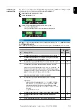
Page 170: ...hosepack NOTE The welding circuit resistance r depends on the hosepack used if the hosepack length or cross sectional area is changed measure the welding cir cuit resistance r again measure the weldi...

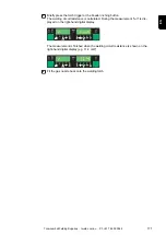
Page 171: ...During the measurement run is dis played on the right hand digital display The measurement is finished when the welding circuit resistance is shown on the right hand digital display e g 11 4 mW 8 Fit...

Page 172: ...Where very high welding circuit inductivity occurs it is also possible to attempt to influ ence the welding results with the droplet detachment correction parameter If this does not produce the desir...

Page 173: ...Troubleshooting and maintenance 173 Toowoomba Welding Supplies tweld com au Ph 61 7 4659 0044...

Page 174: ...174 Toowoomba Welding Supplies tweld com au Ph 61 7 4659 0044...

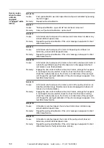
Page 175: ...onnection Displayed service codes If any error message that is not described here appears on the displays then the fault can only be fixed by a service technician Make a note of the error message show...

Page 176: ...nt in wire feed unit drive Arrange the hosepack in as straight a line as possible check that there are no kinks or dirt in the inner liner check the contact pressure on the 2 roller or 4 roller drive...

Page 177: ...rotational speed from the push pull unit motor Check the actual value pick up and the cable connections to and from it and replace if necessary Cause Remedy EFd 15 1 Wire buffer empty Counter lever on...

Page 178: ...o wire buffer missing Check connection to wire buffer check wire buffer control line Cause Remedy EFd 30 1 LHSB connection to power source missing Check LHSB connection to power source Cause Remedy EF...

Page 179: ...n filter or replace acknowledge Err 056 by pressing the Store button Excessive ambient temperature on the VR 1500 11 12 30 Reduce ambient temperature if necessary position and operate welding machine...

Page 180: ...ause Remedy Err Cfg Can only occur when power sources are being operated in parallel or in Twin mode Power source is configured for parallel operation setup parameter P C is set to ON or TimeTwin Digi...

Page 181: ...triggered Cause Remedy no H2O Cooling unit flow watchdog has been triggered Check the cooling unit top up with coolant or bleed the water flow if neces sary see cooling unit operating instructions The...

Page 182: ...r source Allow power source to cool down Cause Remedy tP3 xxx Note xxx is a temperature value Overtemperature in the primary circuit of the power source Allow power source to cool down Cause Remedy tP...

Page 183: ...uit Allow power source to cool down Cause Remedy Power source does not function Mains switch is on but indicators are not lit up There is a break in the mains lead the mains plug is not plugged in Che...

Page 184: ...ice Cause Remedy Cause Remedy Cause Remedy Cause Remedy No welding current Mains switch is ON and indicators are lit up Grounding earthing connection is incorrect Check the grounding earthing connecti...

Page 185: ...ground earth connection Ensure good contact to workpiece Inadequate or no protective gas shield Check the pressure regulator gas hose gas solenoid valve torch gas con nection etc Welding torch is lea...

Page 186: ...medy Cause Remedy Cause Remedy Cause Remedy Cause Remedy Wirefeed problems when using long hosepacks Incorrect arrangement of hosepack Arrange the hosepack in as straight a line as possible avoid tigh...

Page 187: ...ry start up Check mains plug mains cable welding torch interconnecting hosepack and grounding earthing connection for damage Check whether the all round clearance of 0 5 m 1 ft 8 in is kept to ensure...

Page 188: ...188 Toowoomba Welding Supplies tweld com au Ph 61 7 4659 0044...

Page 189: ...Appendix 189 Toowoomba Welding Supplies tweld com au Ph 61 7 4659 0044...

Page 190: ...190 Toowoomba Welding Supplies tweld com au Ph 61 7 4659 0044...

Page 191: ...ax at PCC 2 95 mOhm Primary continuous current 100 d c 3 6 6 A Primary continuous power 4 5 8 7 kVA Cos phi 0 99 Efficiency 87 Welding current range MIG MAG 3 270 A Rod electrode 10 270 A TIG 3 270 A...

Page 192: ...t 230 400 V and 50 Hz 2 PCC Interface to the public grid 3 d c Duty cycle TPS 2700 MV Mains voltage 3 x 200 240 V 3 x 380 460 V Mains voltage tolerance 10 Mains frequency 50 60 Hz Mains fuse protectio...

Page 193: ...Max permitted wirespool weight 16 kg 35 27 lb Wirespool diameter 300 mm 11 81 in Wire diameter 0 8 1 6 mm 0 03 0 06 in Drive 4 roller drive Maximum shielding gas pressure 7 bar 101 psi The wire feed u...

Page 194: ...class F EMC emission class A Marks of conformity CE Safety symbol S Dimensions l x w x h 626 x 287 x 477 mm 24 65 x 11 30 x 18 78 in Weight 34 6 kg 76 3 lb 1 connected to public grid at 230 400 V and...

Page 195: ...lass A Marks of conformity CE CSA Safety symbol S Dimensions l x w x h 626 x 287 x 477 mm 24 65 x 11 30 x 18 78 in Weight 34 6 kg 76 3 lb 1 connected to public grid at 230 400 V and 50 Hz 2 d c Duty c...

Page 196: ...ge 320 A 49 1 63 1 V Open circuit voltage 64 67 V Degree of protection IP 23 Type of cooling AF Insulation class F EMC emission class A Marks of conformity CE CSA Safety symbol S Dimensions l x w x h...

Page 197: ...cooling AF Insulation class F EMC emission class A Marks of conformity CE CSA Safety symbol S Dimensions l x w x h 626 x 287 x 477 mm 24 65 x 11 30 x 18 78 in Weight 35 2 kg 77 6 lb 1 connected to pu...

Page 198: ...sion class A Marks of conformity CE CSA Safety symbol S Dimensions l x w x h 626 x 287 x 477 mm 24 65 x 11 30 x 18 78 in Weight 35 2 kg 77 6 lb 1 connected to public grid at 230 400 V and 50 Hz 2 d c...

Page 199: ...287 x 477 mm 24 65 x 11 30 x 18 78 in Weight 35 6 kg 78 5 lb 1 connected to public grid at 230 400 V and 50 Hz 2 d c Duty cycle TS TPS 5000 MV Mains voltage 3 x 200 240 V 3 x 380 460 V Mains voltage t...

Page 200: ...230 400 V and 50 Hz 2 d c Duty cycle Technical data US devices See TPS 2700 MV 3200 MV and TS TPS 4000 MV 5000 MV Technical data Alu edition CrNi edition Yard edi tion and CMT variants The technical...

Page 201: ...n class F EMC emission class A Marks of conformity CE Safety symbol S Dimensions l x w x h 626 x 287 x 477 mm 24 65 x 11 30 x 18 78 in Weight 37 4 kg 82 45 lb 1 connected to public grid at 230 400 V a...

Page 202: ...w x h 625 x 290 x 705 mm 24 61 x 11 42 x 27 76 in Weight 54 2 kg 119 49 lb 1 connected to public grid at 230 400 V and 50 Hz 2 d c Duty cycle CMT 4000 Advanced MV Mains voltage 3 x 200 240 V 3 x 380 4...

Page 203: ...it voltage 90 V Degree of protection IP 23 Type of cooling AF Insulation class F EMC emission class A Marks of conformity CE CSA Safety symbol S Dimensions l x w x h 625 x 290 x 705 mm 24 61 x 11 42 x...

Page 204: ...R308 Ar 97 5 CO2 2 5 AlMg 5 ER5356 Ar 100 AlSi 5 ER4043 Ar 100 CuSi 3 ER CuSi A Ar 100 SP2 P 0074 S 0008 P 0346 S 1084 P 0378 S 0375 P 0148 S 0149 P 0421 S 0102 P 0345 S 0033 P 0076 S 0009 C P 0959 P...

Page 205: ...t out In position Aut the cut out is automatic depending on the coolant temperature In position On Off the cooling unit remains permanently switched on switched off Separate adjustment for the MIG MAG...

Page 206: ...em FCO Feeder control Wire feed unit cut out wire end sensor option Fdc Feeder creep Feeder creep speed Fdi Feeder inching Feeder inching speed Terms and abbre viations G I GAS Gasflow Set value for s...

Page 207: ...boundary high for the welding power job correction PcL Power correction Low Correction boundary low for the welding power job correction PPU Push pull unit r r resistance Determine welding circuit res...

Page 208: ...urrent duration t S time Starting current Starting current duration tri Trigger Subsequent correction of the mode Uco U Voltage cut off Welding voltage limitation during MMA welding Makes it possible...

Page 209: ...209 EN Toowoomba Welding Supplies tweld com au Ph 61 7 4659 0044...

Page 210: ...210 Toowoomba Welding Supplies tweld com au Ph 61 7 4659 0044...

Page 211: ...211 EN Toowoomba Welding Supplies tweld com au Ph 61 7 4659 0044...

Page 212: ...Toowoomba Welding Supplies tweld com au Ph 61 7 4659 0044...

Reviews: