59
EN-US
Finally...
General
-
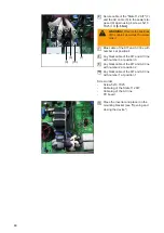
Isolate the inverter in its unloaded state from the AC grid and the DC power supply (set
DC disconnector to level 0).
-
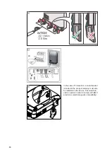
Refit and attach all removed Datcom lines (restore inverter to original state prior to the
repair or safety inspection).
-
If necessary, reinstall the AC lead in the PG screw joint.
-
Check whether conductive objects are deposited in the housing.
-
Mount Datcom lid with 4 screws 5x25 TX25 –
2.5 Nm
General
Deficiencies identified that may be the cause of other hazards must be repaired immedi-
ately, otherwise further use must be restricted until the defect is rectified.
-
Missing or damaged housing parts, insulating parts, or protective covers.
-
Soiling and blockage of cooling vents.
-
Check that safety labels are present (such as warning notices, grounding symbols, rat-
ing plates) and replace, supplement, or correct if necessary.
-
Ensure that all safety-related labels or symbols, rated values and position indicators
are legible.
Summary of Contents for Eco 15.0-3-208 US
Page 2: ...2...
Page 4: ...4...
Page 5: ...Allgemeine Informationen...
Page 6: ......
Page 8: ...8 Mess und Pr f mittel Digitales Multimeter Equipment f r die sicherheitstechnische berpr fung...
Page 9: ...Einbau State 112 KIT...
Page 10: ......
Page 15: ...15 DE 1 2 3 4 5 1 2 3 4 22 1 lbf in 2 5 Nm 5...
Page 19: ...Sicherheitstechnische berpr fung...
Page 20: ......
Page 32: ...32...
Page 34: ...34...
Page 35: ...General Information...
Page 36: ......
Page 38: ...38 Measuring and In spection Equip ment Digital multimeter Equipment for safety inspection...
Page 39: ...Installation State 112 KIT...
Page 40: ......
Page 45: ...45 EN US 1 2 3 4 5 1 2 3 4 22 1 lbf in 2 5 Nm 5...
Page 49: ...Safety inspection...
Page 50: ......
Page 62: ...62...
Page 63: ...63 EN US...


