54
Electrical Tests
Insulation Resis-
tance
The inspections must be carried out with an open lid. Measurement of insulation resistance
must be carried out separately at the mounting bracket and at the inverter!
-
A clear understanding of the tests is required before beginning the work.
-
The inverter must be removed from the mounting bracket.
-
Ensure the device to be checked has been securely disconnected from the AC grid
(mains power line [L and N] must not be connected). If the AC grid cannot be discon-
nected from the mounting bracket, all GND terminals must be checked for the correct
torque.
-
Strings must not be completed at the mounting bracket. The insulation resistance test
can be carried out with module group connected.
-
During the measurements, all switches (DC disconnector on level I), controllers, etc.
must be closed.
-
Disconnection from Fronius SolarNet and Datcom Ring is required.
-
The insulation resistance test must be carried out with correct polarity.
During the test, insulation may not fall below the following values. The specified test volt-
ages must be observed *):
*) These requirements relate to DIN VDE 0701-0702 and ÖVE/ÖNORM E8701-1. In addi-
tion, individual national requirements and standards must also be observed.
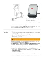
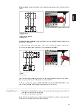
Legend: Primary = DC (DC+ and DC-) | Secondary = AC (L and N) | Ground = PE
Insulation resistance must be measured between the following points, both at the inverter
as well as at the mounting bracket:
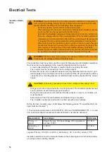
WARNING!
An electric shock can be fatal. Insulation resistance is measured, in
part, using high voltage. Before the test is started, the procedure must be com-
pletely understood. Adhere to the following safety measures:
-
As far as possible, restrict access to the working area.
-
When carrying out the test, do not touch any other people and take measures
to ensure that no other people touch metal surfaces.
-
Each time the insulation resistance measurement instrument is switched on,
there is a voltage present at the area being tested. The insulation resistance
measurement instrument must be fitted with an automatic self discharge unit.
-
Throughout the test, suitable protective clothing/equipment must be worn.
-
When carrying out the insulation resistance test, do not touch any other peo-
ple and take measures to ensure that no other people touch the back of the
solar module or the terminals of the solar module with any body parts.
-
Ensure that the insulation resistance test is carried out with the correct polar-
ity, as incorrect polarity may lead to incorrect measurement results.
WARNING!
As the module group voltage has not been isolated at the mounting
bracket, the PV voltage remains at the terminals.
CAUTION!
Take safety precautions. Due to DC voltage, follow safety rules!
Measurement
Test voltage
Limit value
Primary –>
ground
At least the max. DC input voltage of the equipment,
but max. 1000 V
>= 1 M
Secondary –>
ground
>= 500 V
>= 1 M
Summary of Contents for Eco 15.0-3-208 US
Page 2: ...2...
Page 4: ...4...
Page 5: ...Allgemeine Informationen...
Page 6: ......
Page 8: ...8 Mess und Pr f mittel Digitales Multimeter Equipment f r die sicherheitstechnische berpr fung...
Page 9: ...Einbau State 112 KIT...
Page 10: ......
Page 15: ...15 DE 1 2 3 4 5 1 2 3 4 22 1 lbf in 2 5 Nm 5...
Page 19: ...Sicherheitstechnische berpr fung...
Page 20: ......
Page 32: ...32...
Page 34: ...34...
Page 35: ...General Information...
Page 36: ......
Page 38: ...38 Measuring and In spection Equip ment Digital multimeter Equipment for safety inspection...
Page 39: ...Installation State 112 KIT...
Page 40: ......
Page 45: ...45 EN US 1 2 3 4 5 1 2 3 4 22 1 lbf in 2 5 Nm 5...
Page 49: ...Safety inspection...
Page 50: ......
Page 62: ...62...
Page 63: ...63 EN US...


