background image

61

EN-US

Documentation

Documentation

-

The electrician who carried out the inspections is responsible for documenting them 
correctly

-

All inspections carried out are to be documented in an inspection log. The measured 
values as well as the inspection equipment used, and calibration data must be given.

-

If an individual inspection cannot be carried out, reasons for the inspector's decision 
are to be documented.

-

If the inspection is not passed, then the device in question must be clearly identified 
as unsafe and the operator must be informed. The equipment must no longer be op-
erated.

Summary of Contents for Eco 15.0-3-208 US

Page 1: ...Welding Solar Energy 42 0410 2321 003 19052017 Fronius Eco Fronius Symo 15 0 3 208 US Installationsanleitung Netzgekoppelter Wechselrichter Installation Instructions Inverter for grid connected photo...

Page 2: ...2...

Page 3: ...heitstechnische berpr fung 21 Sicherheitstechnische berpr fung 21 Verantwortlichkeit 21 Anwendungsbereich 21 Qualifikation des Pr fpersonals 21 Messinstrumente 21 Sichtpr fungen 23 Allgemeines 23 Netz...

Page 4: ...4...

Page 5: ...Allgemeine Informationen...

Page 6: ......

Page 7: ...ef hrt werden Beachten Sie das Kapitel Sicherheitsvorschriften in der Bedienungsan leitung des Wechselrichters WARNUNG Ein elektrischer Schlag kann t dlich sein Vor ffnen des Ger tes Netzschalter in S...

Page 8: ...8 Mess und Pr f mittel Digitales Multimeter Equipment f r die sicherheitstechnische berpr fung...

Page 9: ...Einbau State 112 KIT...

Page 10: ......

Page 11: ...Hilfe eines geeigneten Messger tes sicherstellen dass elektrisch gela dene Bauteile z B Kondensatoren entladen sind WARNUNG Ein elektrischer Schlag kann t dlich sein Gefahr durch Restspan nung von Kon...

Page 12: ...ung zur Montagehalterung l sen Wechselrichter nach oben hin aush n gen EMV B gel demontieren 6 Stk Schraube 5x16 TX25 4 l sen und Leistungsteil Deckel abnehmen 1 2 2 WARNUNG Sicherheitsvorschrift en b...

Page 13: ...en 2 Stk Schraube 5x25 TX25 3 montie ren und dadurch die feste Verbindung zur Montagehalterung herstellen 2 5 Nm Falls vorhanden s mtliche Steckver bindungen montieren Datcom Deckel mit 4 Stk Schraube...

Page 14: ...bindung kann schwerwiegende Personen und Sachsch den verursachen Die Geh use Schrauben stellen eine geeignete Schutzleiter Verbindung f r die Erdung des Geh uses dar und d rfen keinesfalls durch ander...

Page 15: ...15 DE 1 2 3 4 5 1 2 3 4 22 1 lbf in 2 5 Nm 5...

Page 16: ...s Eco muss zus tzlich ein im Lieferumfang enthaltener Metallb gel auf das Ger t montiert werden Dieser Metall b gel ist notwendig um die EMV Bestim mungen Elektromagnetische Vertr glichkeit einzuhalte...

Page 17: ...urch dieses Loch des EMV K figs 6 f hren State 112 KIT 4 mit den beiliegenden Kabelbindern 5 am EMV K fig 6 be festigen berl nge der Kabelbinder mit einem Seitenschneider entfernen 1 1 1 1 WARNUNG Sic...

Page 18: ...sition 3 Beliebiges schwarzes Kabel des KIT und AC Leitung mit der Nummer 2 auf Position 2 Beliebiges schwarzes Kabel des KIT und AC Leitung mit der Nummer 1 auf Position 1 Schraubreihenfolge Schraube...

Page 19: ...Sicherheitstechnische berpr fung...

Page 20: ......

Page 21: ...Pr fung begonnen wird Kann eine der Pr fungen nicht durchgef hrt werden so ist vom Pr fer zu entscheiden und es obliegt seiner Verantwortung und Haftung ob die Sicherheit des Ger tes trotzdem best ti...

Page 22: ...hmen treffen die das Auftreten von gef hrli chen Ber hrungsspannungen vermeiden Der Messbereich muss mindestens die Werte von 0 25 mA bis 19 mA umfassen Die Pr feinrichtung muss den gemessenen Strom u...

Page 23: ...chutzabdeckungen d rfen nicht fehlen oder besch digt sein Unzul ssige nderungen d rfen nicht vorhanden sein z B Ein Umbauten welche nicht vom Hersteller frei gegeben sind K hl ffnungen d rfen nicht ve...

Page 24: ...er Schlag kann t dlich sein Bei der Isolationswider stands Pr fung wird zum Teil mit Hochspannung gemessen Vor Beginn der Pr fung muss das Verfahren vollst ndig verstanden werden Die folgenden Sicherh...

Page 25: ...geben ist Auf eine sichere Trennung des zu pr fenden Ger tes vom AC Netz ist zu achten Netzleitung L N darf nicht angeschlossen sein Sollte das AC Netz nicht von der Montagehalterung getrennt werden k...

Page 26: ...elrichter angeschlossen wurde diesen wieder in Betrieb nehmen F r die Messung muss der Wechselrichter einspeisen da es sonst zu einem falschen Messer gebnis kommt Es d rfen nur die Ableitstr me herang...

Page 27: ...ms Differenzstrom Verfahren Messung des Schutzleiter Stroms mit Stromzange ber N und L Leiter Wie bei einem FI Schalter werden ber einen Wandler die Str me zwischen den Au en leiter L und dem Neutrall...

Page 28: ...hrstrom darf 0 5 mA nicht bersteigen 1 Messeinrichtung 2 Wechselrichter 6 2 Ber hrbarer leitf higer nicht mit dem Schutzleiter verbundener Teil 8 Isolierte Aufstellung des Pr flings 9 Messleitung Ri...

Page 29: ...chraube 5x25 TX25 montieren 2 5 Nm Allgemeines Erkennbare M ngel die Anlass anderer Gef hrdungen sein k nne m ssen eine sofortige Instandsetzung oder Einschr nkung der weiteren Verwendung bis zur M ng...

Page 30: ...ptschalter und DC Hauptschalter Lastfrei oder bei minimaler Last durchf hren jedoch nicht im Standby Modus DC Hauptschalter ausschalten Wechselrichter muss auf St rung gehen und die Einspeisung unterb...

Page 31: ...koll dokumentieren Sowohl die Messwerte als auch die verwendeten Pr fmittel und Kalibrierdaten angeben Kann eine Einzelpr fung nicht durchgef hrt werden ist diese Entscheidung vom Pr fer zu begr nden...

Page 32: ...32...

Page 33: ...pection 49 Safety inspection 51 Safety Inspection 51 Responsibility 51 Scope of Application 51 Qualification of the Inspection Personnel 51 Measuring Instruments 51 Visual inspection 53 General 53 Mai...

Page 34: ...34...

Page 35: ...General Information...

Page 36: ......

Page 37: ...Rules chapter in your inverter operating instructions WARNING An electric shock can be fatal Before opening the device Set power switch to O Disconnect the device from the grid Attach a clear warning...

Page 38: ...38 Measuring and In spection Equip ment Digital multimeter Equipment for safety inspection...

Page 39: ...Installation State 112 KIT...

Page 40: ......

Page 41: ...Use a suitable measuring instrument to ensure that electrically charged com ponents e g condensers are discharged WARNING An electric shock can be fatal Danger of residual voltage from ca pacitors Wai...

Page 42: ...atcom area and loosen the connection to the mounting bracket Detach the inverter from above Remove EMC bracket loosen 6 screws 5x16 TX25 4 and remove po wer stage set lid 1 2 2 WARNING Observe the saf...

Page 43: ...nd allow it to engage with the mounting bracket Using 2 screws 5x25 TX25 3 fix to the mounting bracket securely 2 5 Nm If applicable mount all plug connecti onsmounting bracket Mount Datcom lid with 4...

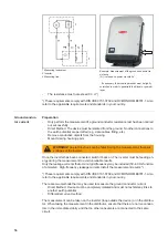
Page 44: ...can cause serious inju ry and damage to property The housing screws provide an adequate ground con ductor connection for grounding the housing and should not be replaced under any circumstances by ot...

Page 45: ...45 EN US 1 2 3 4 5 1 2 3 4 22 1 lbf in 2 5 Nm 5...

Page 46: ...of Fronius Eco a metal bracket included in the scope of delivery must also be installed on the device This metal bra cket is needed in order to comply with EMC provisions electromagnetic compatibilit...

Page 47: ...KIT through this hole of the EMC cage 6 Use enclosed cable ties 5 to secure State 112 KIT 4 to the EMC cage 6 Use diagonal cutting pliers to remove excess length of the cable ties 1 1 1 1 WARNING Obs...

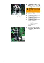
Page 48: ...r 3 at position 3 Any black cable of the KIT and AC line with number 2 at position 2 Any black cable of the KIT and AC line with number 1 at position 1 Screw order Screw 5x10 TX25 Cable lug of the Sta...

Page 49: ...Safety inspection...

Page 50: ......

Page 51: ...safety of the device can still be confirmed This de cision must be justified accordingly and included in the inspection log under Notes Scope of Applica tion In principle a safety inspection must be c...

Page 52: ...he inspection facility must assess the measured current to be an effective value re gardless of the waveform Contact Current The effective inner resistance of the contact current measurement instrumen...

Page 53: ...ctive covers must not be missing or damaged Unauthorized modifications must not be present e g Fittings and modifications not authorized by the manufacturer Ventilation openings must not be soiled or...

Page 54: ...measured between the following points both at the inverter as well as at the mounting bracket WARNING An electric shock can be fatal Insulation resistance is measured in part using high voltage Befor...

Page 55: ...If the AC grid cannot be disconnect ed from the mounting bracket the appropriate safety precautions must be taken Re insert the inverter in the mounting bracket Ground to AC Ground to DC Symo 10 20 Ec...

Page 56: ...en connected switch it back on The inverter must be feeding en ergy during the measurement to avoid unreliable results Only the leakage currents that occur at grid frequency may be included 50 60 Hz f...

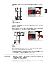
Page 57: ...9 Measuring line Examples of measuring the ground conductor current The ground conductor leakage current must not exceed the limit value of 3 5 mA during this measurement direct or differential curre...

Page 58: ...nd conductor 8 Insulated assembly of the object being tested 9 Measurement lead Ri 1 2 k Touchable conductive parts not connected to the ground conductor These requirements comply with DIN VDE 0701 07...

Page 59: ...sing Mount Datcom lid with 4 screws 5x25 TX25 2 5 Nm General Deficiencies identified that may be the cause of other hazards must be repaired immedi ately otherwise further use must be restricted until...

Page 60: ...main switch and DC main switch carry out with no load or minimal load but not in standby mode Switch off DC main switch Inverter must go into a fault condition and interrupt the feed in Switch off AC...

Page 61: ...pection log The measured values as well as the inspection equipment used and calibration data must be given If an individual inspection cannot be carried out reasons for the inspector s decision are t...

Page 62: ...62...

Page 63: ...63 EN US...

Page 64: ...d all addresses of our sales branches and partner firms Fronius International GmbH 4600 Wels Froniusplatz 1 Austria E Mail pv sales fronius com http www fronius com Fronius USA LLC Solar Electronics D...

Reviews: