background image

3

Installing the
mounting bracket
on a mast or
beam

When installing the inverter on a mast or
support, Fronius recommends the "Pole
Clamp" kit from Rittal GmbH (order no. SZ
2584.000).
This kit enables the inverter to be installed
on round or rectangular masts with the fol-
lowing diameters: Æ from 40 to 190 mm
(round mast), ÿ from 50 to 150 mm (rect-
angular mast)

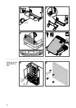
Fitting the mount-
ing bracket to
metal supports

NOTE!

When mounted on metal supports, the inverter must not be exposed to rainwater
or splashing water from the rear.

Provide suitable rainwater protection or splash water protection.

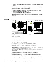
The mounting bracket must be securely screwed to at least four points.

13

EN

Summary of Contents for Eco 25.0-3-M

Page 1: ...elemental chlorine free paper ECF sourced from certified sustainable forests FSC Perfect Charging Perfect Welding Solar Energy Fronius Symo 10 20 kW Fronius Eco EN Installation instructions 42 0426 01...

Page 2: ......

Page 3: ...rters 23 General 23 Multi MPP tracker Fronius Symo M inverter 23 Single MPP tracker Fronius Eco inverter 25 Connecting solar module strings to the inverter 28 Safety 28 General comments regarding sola...

Page 4: ...erial Number Sticker for Customer Use 51 Serial number sticker for customer use 51 DC SPD option 52 Installing the DC SPD option 52 Circuit Diagram 52 Cabling the DC SPD option 53 Settings in the Basi...

Page 5: ...orrectly performed work This can result in serious injury and damage to property Only qualified personnel are authorised to commission your inverter and only within the scope of the respective technic...

Page 6: ...parallel arc Note After an arc has been detected the entire photovoltaic system must be checked for possible damage before resetting the inverter Observe the manufacturer s connection installation and...

Page 7: ...n Install the inverter in a protected location e g in the vicinity of the solar modules or beneath the eaves Fronius Symo UDCmax at an altitude of 0 to 2000 m 1000 V 2001 to 2500 m 950 V 2501 to 3000...

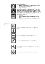
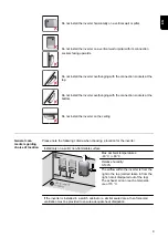
Page 8: ...mend not installing the inverter in areas and environments with high dust accumulation Do not install the inverter in Greenhouses Storage or processing areas for fruit vegetables or viticulture produc...

Page 9: ...ing General com ments regarding choice of location Please note the following criteria when choosing a location for the inverter Install only on a solid non flammable surface Max ambient temperatures 4...

Page 10: ...outer wall of a cattle shed maintain a minimum all round clearance of 2 m between the inverter and all ventilation and other openings in the building The installation location must not be exposed to a...

Page 11: ...mounting bracket and permanently attached using screws the cover for the data communication area is permanently attached to the inverter with screws Degree of protection IP 20 applies to the mounting...

Page 12: ...ON OFF Lock 1 2 3 4 Fitting the mount ing bracket to a wall 1 2 12...

Page 13: ...round or rectangular masts with the fol lowing diameters from 40 to 190 mm round mast from 50 to 150 mm rect angular mast Fitting the mount ing bracket to metal supports NOTE When mounted on metal su...

Page 14: ...1 Do not warp or deform the mounting bracket Note When fitting the mounting bracket to the wall ensure that the mounting bracket does not become warped or deformed 14...

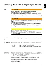
Page 15: ...inverter which may lead to fire When connecting AC and DC cables ensure that all the terminals are tightened to the specified torque Monitoring the grid To provide the best possible grid monitoring t...

Page 16: ...section of each conductor cable 16 mm Min cross section of each conductor cable in accordance with the fuse rating on the AC side but at least 2 5 mm The AC cables can be connected to the AC terminals...

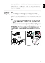
Page 17: ...umstances it may no longer be possible to close the invert er Note Make sure that the grid s neutral conductor is grounded This may not be the case for IT grids insulated grids with no earthing it wil...

Page 18: ...the side underneath the terminals If AC cables are laid over the shaft of the DC main switch or across the connection block of the DC main switch they may be damaged when the inverter is swung in or...

Page 19: ...A Fronius Symo 20 0 3 M 3 20 000 W C 80 A Fronius Eco 25 0 3 M 3 25 000 W C 80 A Fronius Eco 27 0 3 M 3 27 000 W C 80 A Note Local regulations the electricity retailer or other factors may require a...

Page 20: ...us recommends that a residual current circuit breaker that is suitable for frequency con verters should be used 20...

Page 21: ...PV modules the correct fuse protection The maximum string fuse rating per terminal is 20 A The maximum MPP current nominal current operating cur rent Imax is 15 A per string The national regulations r...

Page 22: ...Replacing fuses ON OFF Lock AC OFF 2 CHECK VALUES 22...

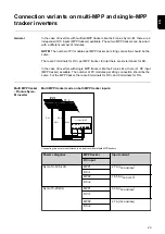
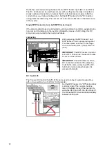
Page 23: ...single MPP trackers like the Fronius Eco there is 1 DC input MPP tracker available The number of PV modules per string connection should be the same For the MPP tracker there are 6 terminals for DC a...

Page 24: ...nnected to the inverter as follows Jumpering DC 1 Pin2 DC 2 Pin1 With jumpering the MPP tracker 1 and MPP tracker 2 can be jumpered together This takes place as shown in the image via the connection D...

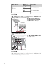
Page 25: ...of the in verter By using the DC Con Kit 35 the DC strings of the connected DC lines are di vided equally between the two inputs PV cable connection torque DC Con Kit 35 3 Nm Single MPP track er Froni...

Page 26: ...p to 25 mm to the inverter Connecting multiple interconnected solar module fields to an inverter with multiple MPP trackers using one lead By using the DC Con Kit 25 the DC strings of the connected DC...

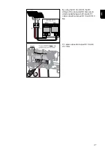
Page 27: ...using the DC Con Kit 35 the DC strings of the connected DC lines are di vided equally between both inputs PV cable connection torque DC Con Kit 35 3 Nm PV cable connection torque DC Con Kit 35 3 Nm 27...

Page 28: ...wer stage set The con nection area is still live when the DC main switch is switched off Ensure that the power stage set and connection area are disconnected from one an other before carrying out any...

Page 29: ...y suitable calculation programs like the Fronius Solar configurator which can be downloaded from http www fronius com Note Before connecting up the solar modules check that the voltage for the solar m...

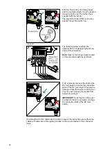
Page 30: ...utral grease such as non acidic and non alkaline Vaseline 3 Immediately connect the cable end to the terminal IMPORTANT Repeat the procedure if the cable has been disconnected and is to be re connecte...

Page 31: ...get break points as the number of cables that are provided e g if there are 2 DC cables then break out 2 recesses Note Fronius Eco check the string fuses used type and rating before connecting the sol...

Page 32: ...5 6 7 Note Observe the torque values marked on the side underneath the terminals 8 9 32...

Page 33: ...connection block of the DC main switch they may be damaged when the inverter is swung in or they may even prevent the inverter from being swung in IMPORTANT Do not lay DC cables over the shaft of the...

Page 34: ...verter observe the fol lowing points Depending on the number and cross section of the data communication cables that are being introduced take the relevant blanking plugs out of the sealing insert and...

Page 35: ...ection IMPORTANT Observe the ESD guidelines when handling option cards IMPORTANT Only one Fronius Datamanager in master mode is permitted per Fronius Solar Net ring Switch any other Fronius Datamanage...

Page 36: ...3 4 5 36...

Page 37: ...inverter to the mounting bracket or swing it in unless the DC main switch is switched off Never use force to attach the inverter or swing it in The fastening screws in the data communication area of...

Page 38: ...1 2 3 4 38...

Page 39: ...5 6 7 39 EN...

Page 40: ...l bracket 1 With the Fronius Eco a metal bracket in cluded in the scope of delivery must also be fitted to the device This metal bracket is required for compliance with EMC elec tromagnetic compatibil...

Page 41: ...re installing and commissioning the equipment When starting the inverter for the first time it is necessary to select various setup set tings If setup is interrupted before it is complete it can be re...

Page 42: ...NA S DK B Danmark 50kW 1 5MW DKA1 West Denmark 125kW DKA2 East Denmark 125kW DU1 Dubai 10 kW DU2 Dubai 10 kW 400 kW DU3 Dubai 400 kW EE Estonia ES Espa a ESOS Territorios espa oles en el extranjero Sp...

Page 43: ...8 9 43 EN...

Page 44: ...er is supplied with a USB flash drive the inverter software must be up dated as soon as the inverter has been commissioned 1 Plug the USB flash drive into the data communication area of the inverter 2...

Page 45: ...inverter that is irrelevant to the customer The file must not be deleted separately Only delete all of the files sys fld csv at one time DALO fld log file A log file for reading the data in the Froni...

Page 46: ...proximately sev en months CSV data size of approx 8 MB In order to avoid data loss the CSV file should be backed up to a PC and deleted from the USB flash drive within this seven month period If the l...

Page 47: ...supply If there is a power failure while the inverter is in operation all the data in the buffer memory will be lost To avoid losing data during the night the automatic night switch off facility must...

Page 48: ...r example at low temperatures USB stick for up dating the invert er software With the help of the USB stick end customers can also update the inverter software via the USB item on the SETUP menu the u...

Page 49: ...ition once a year check that all screw joints are tight Maintenance and servicing may only be carried out by Fronius trained service techni cians Cleaning Clean the inverter as required with a damp cl...

Page 50: ...rable air circulation and condensation in the conduits Seal all conduits being used with a permanently elastic sealant Seal every incoming and outgoing conduit Seal both conduit ends Conduit Conduit A...

Page 51: ...he inverter has been installed in a dark or shaded area Two serial number stickers are enclosed with the inverter s installation instructions 57 x 20 mm 67 x 20 mm These can be affixed by the customer...

Page 52: ...nverter Depending on the device type one surge protective device single MPP tracker or two surge protective devices multiple MPP tracker must be installed in the inverter The surge protective device m...

Page 53: ...SPD option can be ordered built in or retrofitted at a later date The cabling de scribed below must be carried out for both variants The M16 cable gland is included in the scope of delivery DC SPD M...

Page 54: ...3 Settings in the Basic menu 1 3 2 2 1 1 2 1 1 2 3 M o d e o f o p e r a t i o n T r i g g e r r e s p o n s e C o n n e c t i o n t y p e Warning is shown on the display The inverter is switched off...

Page 55: ...M o d e o f o p e r a t i o n T r i g g e r r e s p o n s e C o n n e c t i o n t y p e N C normally closed contact N O normally open contact 55 EN...

Page 56: ...al The inverter can be ordered with the DC plug pair MC4 option Unused connections must be covered with a cover plate The cover plates can be ordered using the following item numbers MC30A DC 43 0003...

Page 57: ...The scope of delivery for the inverter with the DC plug pair MC4 option includes a label with a cable overview This label can be positioned on the inverter in a suitable place 57 EN...

Page 58: ...58...

Page 59: ...59 EN...

Page 60: ......

Reviews: