Connecting the inverter to the public grid (AC side)
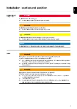
Safety
WARNING!
Danger due to incorrect operation and incorrectly performed work.
This may result in serious injury and damage to property.
▶
Only qualified staff are authorised to commission your inverter and only within the
scope of the respective technical regulations.
▶
Read the Installation and Operating Instructions before installing and commissioning
the equipment.
WARNING!
Danger due to grid voltage and DC voltage from solar modules that are exposed to
light.
This may result in an electric shock.
▶
Ensure that both the AC side and the DC side of the inverter are de-energised be-
fore carrying out any connection work.
▶
Only an authorised electrical engineer is permitted to connect this equipment to the
public grid.
CAUTION!
Danger due to incorrectly tightened terminals.
This may result in heat damage to the inverter, which may lead to fire.
▶
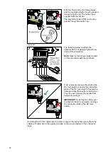
When connecting AC and DC cables, ensure that all the terminals are tightened to
the specified torque.
Monitoring the
grid
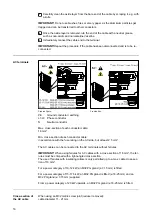
To provide the best possible grid monitoring, the resistance in the leads to the AC-side
terminals should be as low as possible.
Type of AC cable
The following types of AC cable can be connected to the AC terminals of the inverter:
-
Copper or aluminium: solid round conductor
-
Copper: fine-stranded round conductor, up to conductor class 4
Preparing the alu-
minium cables
for connection
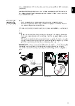
The AC-side terminals are suitable for connecting single-wire, round aluminium cables.
Because of the formation of a non-conductive oxide layer due to the reaction of alumini-
um with air, the following points must be considered when connecting aluminium cables:
-
the reduced rated currents for aluminium cables
-
the connection conditions listed below
Always follow the cable manufacturer instructions when using aluminium cables.
When designing cable cross-sections, take local regulations into account.
Connection conditions:
15
EN
Summary of Contents for Eco 25.0-3-M
Page 2: ......
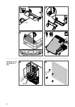
Page 12: ...ON OFF Lock 1 2 3 4 Fitting the mount ing bracket to a wall 1 2 12...
Page 22: ...Replacing fuses ON OFF Lock AC OFF 2 CHECK VALUES 22...
Page 32: ...5 6 7 Note Observe the torque values marked on the side underneath the terminals 8 9 32...
Page 36: ...3 4 5 36...
Page 38: ...1 2 3 4 38...
Page 39: ...5 6 7 39 EN...
Page 43: ...8 9 43 EN...
Page 58: ...58...
Page 59: ...59 EN...
Page 60: ......

