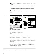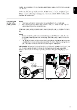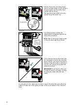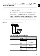
Connecting alu-
minium cables
The DC-side terminals are suitable for connecting single-wire, round aluminium cables.
Because of the formation of a non-conductive oxide layer due to the reaction of alumini-
um with air, the following points must be considered when connecting aluminium cables:
-
the reduced rated currents for aluminium cables
-
the connection conditions listed below
Note!
Always follow the cable manufacturer instructions when using aluminium cables.
Note!
When designing cable cross-sections, take local regulations into account.
Connection conditions:
1
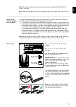
Carefully clean the oxide layer from the bare end of the cable by scraping it, e.g. with
a knife
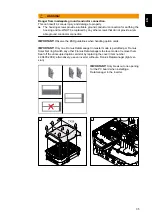
IMPORTANT!
Do not use brushes, files or emery paper, as the aluminium particles get
trapped and can be transferred to other conductors.
2
Once the oxide layer is removed, rub the end of the cable with a neutral grease,
such as non-acidic and non-alkaline Vaseline
3
Immediately connect the cable end to the terminal
IMPORTANT!
Repeat the procedure if the cable has been disconnected and is to be re-
connected.
Solar module
strings - check-
ing the polarity
and voltage
CAUTION!
Danger due to incorrect polarity and voltage.
This may result in damage to the inverter.
▶
Check the polarity and voltage of the solar module strings before making the con-
nection. The voltage must not exceed the following values:
▶
Fronius Symo:
▶
When installed between 0 and 2000 m above sea level: 1000 V
▶
When installed between 2001 and 2500 m above sea level: 950 V
▶
When installed between 2501 and 3000 m above sea level: 900 V
▶
When installed between 3001 and 3400 m above sea level: 850 V
▶
the Fronius Symo must not be installed at an altitude exceeding 3400 m above sea
level
▶
Fronius Eco:
▶
When installed between 0 and 2000 m above sea level: 1000 V
▶
When installed between 2001 and 2500 m above sea level: 950 V
▶
the Fronius Eco must not be installed at an altitude exceeding 2500 m above sea
level
30
Summary of Contents for Eco 25.0-3-M
Page 2: ......
Page 12: ...ON OFF Lock 1 2 3 4 Fitting the mount ing bracket to a wall 1 2 12...
Page 22: ...Replacing fuses ON OFF Lock AC OFF 2 CHECK VALUES 22...
Page 32: ...5 6 7 Note Observe the torque values marked on the side underneath the terminals 8 9 32...
Page 36: ...3 4 5 36...
Page 38: ...1 2 3 4 38...
Page 39: ...5 6 7 39 EN...
Page 43: ...8 9 43 EN...
Page 58: ...58...
Page 59: ...59 EN...
Page 60: ......

