background image

10

Installation information

Selecting dowels 
and screws

Screw Recom-
mendation

To install the inverter, the manufacturer recommends using steel or aluminum screws with 
a diameter of 0.2–0.3 in. (6–8 mm).

Attaching the 
Wall Bracket

IMPORTANT! 

Depending on the surface, different mounting materials may be required for 

installing the wall bracket. These mounting materials are not part of the scope of delivery 
for the inverter. The installer is responsible for selecting the proper mounting materials.

NOTE! 

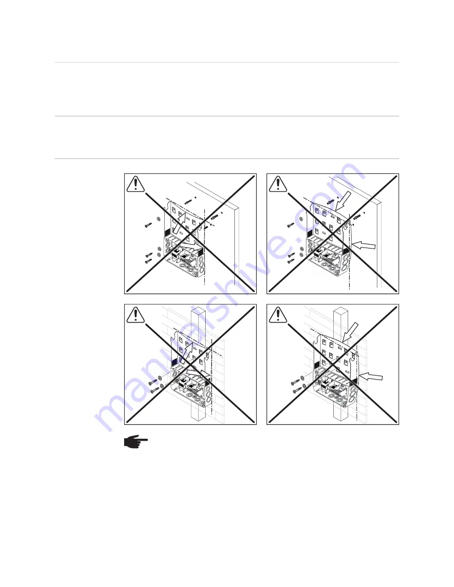
When attaching the wall bracket to the wall or a pillar, make sure that the 

wall bracket is not warped or deformed.

Summary of Contents for Galvo 208-240 1.5-1

Page 1: ...ing Solar Energy 42 0426 0182 EA 011 19122016 Fronius Galvo 208 240 Symbol Explanations and Choosing the Location Notes on Installation and Connection Operating Instructions Inverter for grid connecte...

Page 2: ...2...

Page 3: ...or DC disconnect 16 Notes on Solar Module Grounding in the Inverter 17 Notes on Solar Module Grounding in the Inverter 17 Notes on DC Connection 19 General Information about Solar Modules 19 Inverter...

Page 4: ...4...

Page 5: ...ropriate precautions are not taken NOTE Indicates the possibility of flawed results and damage to the equipment IMPORTANT Indicates tips for correct operation and other particularly useful information...

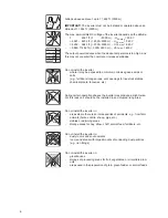
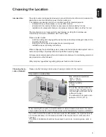
Page 6: ...eries etc During certain operation phases the inverter may produce a slight noise For this reason it should not be installed in an occupied living area Do not install the inverter in areas where there...

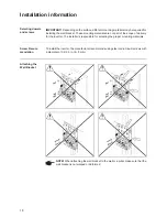
Page 7: ...o not install the inverter on an inclined surface with the connection sockets facing upwards Do not install the inverter in a sloping position on a vertical wall or pillar Do not install the inverter...

Page 8: ...8 Do not install the inverter so that it is overhanging with the connection sockets facing downwards Do not install the inverter on the ceiling...

Page 9: ...g completely within their permitted operating range All measures recommended by the solar module manufacturer for maintaining solar mod ule properties must be followed Utility company regulations rega...

Page 10: ...ing the Wall Bracket IMPORTANT Depending on the surface different mounting materials may be required for installing the wall bracket These mounting materials are not part of the scope of delivery for...

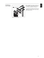
Page 11: ...n installing the inverter on a mast or a vertical pillar Fronius recommends using a commercially available mast fixing set The mast fixing set allows the inverter to be installed on a round or square...

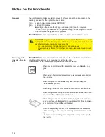
Page 12: ...may cause short circuits when the inverter is powered up When removing knockouts make sure that no loose metal parts fall into the inverter connection area any metal pieces that do fall into the conne...

Page 13: ...08 V Delta without neutral conductor 208 V Delta 120 V WYE with neutral conductor 220 V Delta without neutral conductor 220 V Delta 127 V WYE with neutral conductor 240 V Delta without neutral conduct...

Page 14: ...de layer of the stripped end of the cable e g using a knife IMPORTANT Do not use brushes files or sandpaper aluminum particles may get stuck and can transfer to other cables After removing the oxide l...

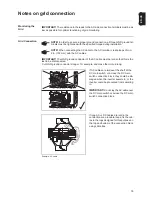
Page 15: ...he AC cable over the DC main switch or across the DC main switch connection block Example AC cable If long AC or DC cables are laid in the connection area in cable loops fix the cab les to the lugs de...

Page 16: ...e inverter is installed in a location not easily accessible to utility or fire personnel Contact your local authorities for additional information AC max 20 A Inverter Number of phases Max output Max...

Page 17: ...is located on the back of the inverter The inverter can also be operated with solar modules which require grounding at the pos itive pole IMPORTANT The solar module is not grounded at the positive pol...

Page 18: ...Remove GFDI fuse from the inverter Mount the GFDI fuse outside of the in verter Adjust the ground settings in the BA SIC menu DC DC N GND L1 L2 DC DC N GND L1 L2 Solar modules ground at the negative p...

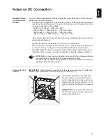
Page 19: ...calculation tools such as the Fronius Configuration Tool available at http www solarweb com See NEC table 690 7 for the appropriate code related voltage adjustment factor for crystalline silicon modu...

Page 20: ...knock out the corresponding opening clean the knocked out opening insert the supplied cable bushing into the opening if both openings have been knocked out an additional cable bushing 42 0405 2019 is...

Page 21: ...3 2 x TX25 5 22 13 lb in 1 84 ft lb 2 5 Nm NOTE For safety reasons the in verter is fitted with a locking mech anism which only allows the inverter to be swiveled into the wall bracket when the DC ma...

Page 22: ...e fixing screw upwards from the other side e g using needle nose pliers Undo the fixing screw Installing the Anti Theft Device IMPORTANT Please refer to the instructions for attaching the inverter to...

Page 23: ...23 EN US Fit the padlock to the anti theft device 2 2 1 max 0 28 in 7 mm 8...

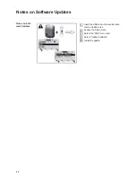
Page 24: ...are Updates Notes on Soft ware Updates Insert the USB stick in the inverter data communication area Access the Setup menu Select the USB menu item Select Update Software Install the update USB 3 5 4 4...

Page 25: ...to the customer The file must not be deleted individually Only delete all files together sys fld csv DALO fld log file Log file for reading out data in Fronius Solar access You can find additional inf...

Page 26: ...e written within approx 7 months CSV data size of approx 8 MB To avoid a loss of data the CSV file should be backed up to a PC within these 7 months and deleted from the USB stick If the logging inter...

Page 27: ...Display ing and Setting Parameters in the DATCOM Menu Item On the Fronius Eco the buffer memory also functions with just a DC supply Suitable USB Sticks Due to the number of USB sticks on the market...

Page 28: ...to the inverter The update file must be saved in the USB stick root directory Removing the USB Stick Safety information for removing a USB stick IMPORTANT To prevent a loss of data the connected USB...

Page 29: ...ed personnel Cleaning The inverter and the display can be cleaned with a damp cloth if necessary Do not use any cleaning agents abrasive cleaners or solvents to clean the inverter NOTE For horizontal...

Page 30: ...lled in a dark or shaded area Two serial number stickers are enclosed with the installation instructions for the in verter 57 x 20 mm 67 x 20 mm The customer can attach these stickers themselves in a...

Page 31: ...31 EN US...
Page 32: ...d all addresses of our sales branches and partner firms Fronius International GmbH 4600 Wels Froniusplatz 1 Austria E Mail pv sales fronius com http www fronius com Fronius USA LLC Solar Electronics D...

Reviews: