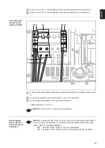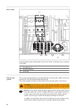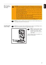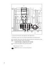
44
Inserting and
connecting op-
tion cards
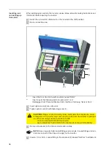
When adding option cards to the inverter, please follow all inverter safety instructions and
information before opening the inverter.
Switch the AC and DC disconnect on the inverter to the OFF position
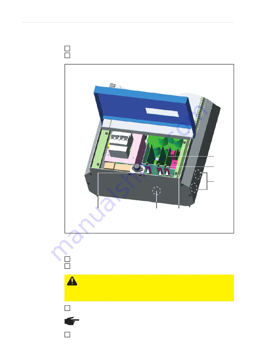
Open connection area
*
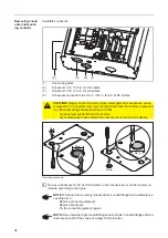
Insert the Com Card in the left-most slot named "ENS"
**
Insert any of the following cards in option slot 1 or 2:
Datalogger Card, Personal Display Card, Interface Card easy, Sensor Card
Insert option card (2) into a free slot
Tighten option card (2) with fastening screw (1)
Remove knockouts (3) for data communication cables
Insert a 1/2 or 3/4 in. conduit fitting in the knockout (3) labeled "DatCom" and fasten it
1
2
CAUTION!
Danger of short circuit by loose metal parts from knockouts. Loose
metal parts in the inverter may cause short circuits when the inverter is powered
up. When removing knockouts, make sure that
-
no loose metal parts fall into the inverter,
-
any metal pieces that do fall into the inverter are removed immediately.
NOTE!
Use only water tight conduit fittings and conduits. Conduit fittings and con-
duits are not part of the scope of supply for the inverter.
**
(3)
(2)
*
(1)
(3)
3
4
5
6
Summary of Contents for IG 2000
Page 2: ...0...
Page 4: ...2...
Page 6: ...4...
Page 10: ...8...
Page 15: ...General Information...
Page 16: ......
Page 21: ...Installation and Startup...
Page 22: ......
Page 50: ...48...
Page 51: ...Operation...
Page 52: ......
Page 80: ...78...
Page 81: ...Troubleshooting and Maintenance...
Page 82: ......
Page 95: ...Appendix...
Page 96: ......
Page 113: ...111 EN US...
Page 114: ...112...
Page 115: ...113 EN US...

