53
EN-US
Operating Status
LED and GFDI
Status LED
Position of Operating Status LED (A) and
the GFDI Ststus LED (B) on the inverter
Depending on the operating status, the
Operating Status LED assumes different
colors:
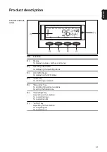
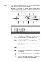
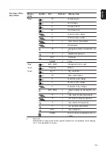
... appears with data readings that are transmitted by the consumption
sensor (optional)
(7)
Range for display unit
for displaying the applicable measuring unit
(8)
Icon for the "Enter" key
(9)
Icons for the "Menu/Esc" key
(10)
Icons for the "Down/Right" key
(11)
Icons for the "Left/Up" key
(12)
Range for display value
for displaying the value
(13)
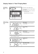
Output bar (not active during setup)
indicates the output power fed into the grid at a given moment - regardless of the
display mode chosen. The screen displays % of the maximum possible output
power of your solar inverter
Item
Function
(A)
(B)
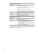
Operating Status LED
(A)
Explanation
Steady green
The LED stays lit after the automatic startup phase of the invert-
er as long as power is being fed into the grid.
It indicates problem-free operation of the photovoltaic system.
Flashing green
The photovoltaic system is working correctly, a status code is on
the display.
When a status code is shown, rectify the relevant condition by
going to the "Maintenance and Service" chapter, "Status Diag-
nosis and Troubleshooting" section. The status code can be ac-
knowledged by pressing the "Enter" key.
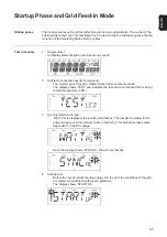
Steady orange
The inverter enters an automatic startup phase as soon as the
solar modules are delivering sufficient power after sunrise.
Summary of Contents for IG 2000
Page 2: ...0...
Page 4: ...2...
Page 6: ...4...
Page 10: ...8...
Page 15: ...General Information...
Page 16: ......
Page 21: ...Installation and Startup...
Page 22: ......
Page 50: ...48...
Page 51: ...Operation...
Page 52: ......
Page 80: ...78...
Page 81: ...Troubleshooting and Maintenance...
Page 82: ......
Page 95: ...Appendix...
Page 96: ......
Page 113: ...111 EN US...
Page 114: ...112...
Page 115: ...113 EN US...


