26
3
2
6 x
4
6
7
1
5
2
3
2
2
2
3
4
1
6
5
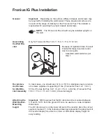
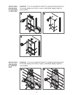
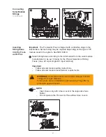
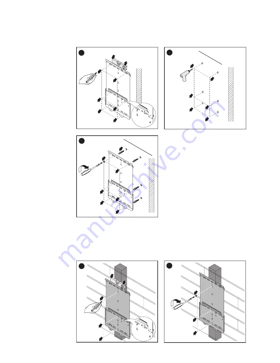
Important
The cut out segment marked (*) represents the placement of
the inverter display. Use this to ensure a comfortable display height for
easy reading.
1
2
1
1
7
3
5
4
6
(*)
Attaching the
Wall Bracket
to a Concrete
or Brick Wall
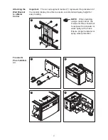
Attaching the
Wall Bracket
to a Wooden
Wall
9
1
1
1
2
3
4
(*)
9
2
1
2
5
Important
The cut out segment marked (*) represents the placement of
the inverter display. Use this to ensure a comfortable display height for
easy reading.
Summary of Contents for IG Plus 12.0-3
Page 2: ......
Page 4: ...ud_fr_st_et_01382 012008...
Page 6: ......
Page 16: ...6...
Page 17: ...7 General Information...
Page 18: ...8...
Page 24: ...14...
Page 25: ...15 Installation and Startup...
Page 26: ...16...
Page 80: ...70...
Page 81: ...71 Operation...
Page 82: ...72...
Page 122: ...112...
Page 123: ...113 Troubleshooting and Maintenance...
Page 124: ...114...
Page 149: ...139 Appendix...
Page 150: ...140...

