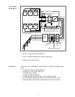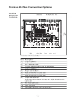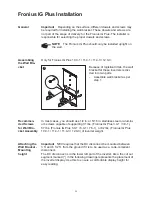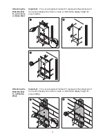
32
AC-side and
Grounding
Terminals
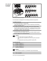
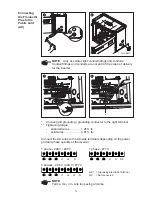
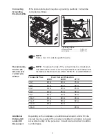
The terminals are designed for the following terminal connections:
Grounding Terminals:
(1) Grounding Electrode Terminal (GET)
A grounding electrode conductor may be required by the Authority
Having Jurisdiction (AHJ).
(2) Equipment grounding (e.g. grounding of the solar module frame)
The PV array (frame) ground should be connected to the Grounding
Terminal. The size for the conductor is usually based on the size of
the largest conductor in the DC system.
(3) Grid grounding / Grounding conductor
The Fronius IG Plus Inverter must be connected to the AC ground
from the utility via the Ground Terminal.
NOTE
-
Use copper wire for all grounding wires.
-
Use only solid or stranded wire. Do not use fine stranded
wire.
-
For appropriate grounding see NEC Section 250.
AC-side Terminals:
L1
= Phase conductor L1
L2
= Phase conductor L2
L3
= Phase conductor L3
N
= Neutral conductor N
NOTE
The neutral conductor is not bonded to ground internally.
N.C. = Not connected
max. wire cross section AWG 4
(1)(2) (3)
AC-side and Grounding Terminals
1-phase inverters 208 V / 240 V
1-phase inverters 277 V
3-phase inverters 208 V / 240 V / 277 V
L1
L2
N
N.C.
L1
N
L3
L1
L2
N
GET
GET
GET
Summary of Contents for IG Plus 12.0-3
Page 2: ......
Page 4: ...ud_fr_st_et_01382 012008...
Page 6: ......
Page 16: ...6...
Page 17: ...7 General Information...
Page 18: ...8...
Page 24: ...14...
Page 25: ...15 Installation and Startup...
Page 26: ...16...
Page 80: ...70...
Page 81: ...71 Operation...
Page 82: ...72...
Page 122: ...112...
Page 123: ...113 Troubleshooting and Maintenance...
Page 124: ...114...
Page 149: ...139 Appendix...
Page 150: ...140...

