background image

47

7

3

1/2 in.

2

1

DC-

8

2

3

6x

4

3

1

DC-

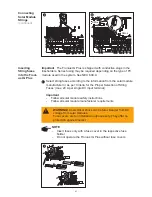
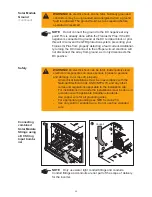
Connecting
combined
Solar Module
Strings using
a DC String
Input Combi-
ner

(continued)

1.33 ft. lb.

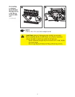
CAUTION!

 Danger of damaging the inverter by overload.

Bevore starting up the inverter make sure, that a conductive
slug is inserted in each fuse holder for string fuses.
-

Insert conductive slugs only with a fuse cover in the respec-
tive fuse holder

-

Do not operate the Fronius IG Plus without fuse covers

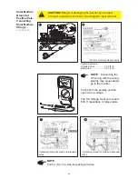
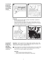
NOTE

Form a min. 4 in. wire loop using all wires.

Summary of Contents for IG Plus 12.0-3

Page 1: ...Fronius IG Plus 3 0 1 3 8 1 5 0 1 6 0 1 7 5 1 10 0 1 11 4 1 11 4 3 12 0 3 42 0426 0071 EA 042008 Operating Instructions USA Inverter for grid connected photo voltaic systems...

Page 2: ......

Page 3: ...e read it carefully to learn about the many great features of your new Fronius product This is the best way to get the most out of all the advantages that it has to offer Please also note the safety i...

Page 4: ...ud_fr_st_et_01382 012008...

Page 5: ...and follow all instructions and safety instructions in this manual Safety Instruc tions The following section Safety Instructions contains different Warnings A Warning describes a hazard to equipment...

Page 6: ......

Page 7: ...followed these operating instructions The operating instructions must be available at the equipment location at all times In addition to the operating instructions all applicable local rules and regul...

Page 8: ...and warning signs are located on the equipment please refer to the General section of your equipment s operating instructions Any equipment malfunctions which might impair safety must be remedied imm...

Page 9: ...e rating plate Care must be taken during installation to ensure that there is no electromag netic interference with electrical and electronic equipment EMC Precautions Danger of damage to electronic c...

Page 10: ...reserved The contents of the operating in structions shall not provide the basis for any claims whatsoever on the part of the purchaser We would be grateful for any comments or suggestions regarding...

Page 11: ...ronius IG Plus Installation and Connection 17 Safety 17 Fronius IG Plus Construction 17 Connection Diagramm 18 Overview 18 Fronius IG Plus Connection Options 19 Fronius IG Plus Connection Options 19 K...

Page 12: ...String Fuses 42 DC disconnect requirements 42 General 42 Criteria for the Proper Selection of String Fuses 42 Effects of using underrated fuses 42 Fuse Recommendations Application Example 43 Fuses 43...

Page 13: ...eration 60 Selecting the public grid 61 Startup Phase at Startup Operation 63 Inserting Option Cards 65 Suitable Option Cards 65 Safety 65 Opening the Fronius IG Plus 65 Inserting Option Cards 66 Conn...

Page 14: ...ng menu item TIME 104 Displaying menu item STATEps 107 Displaying menu item VERSIon 108 Troubleshooting and Maintenance 113 Status Diagnosis and Troubleshooting 115 Displaying Status Codes 115 Normal...

Page 15: ...1 151 Fronius IG Plus 11 4 1 153 Fronius IG Plus 11 4 3 155 Fronius IG Plus 12 0 3 157 Field adjustable trip points 159 Relevant Standards and Directives 160 Relevant Standards and Directives 160 Gri...

Page 16: ...6...

Page 17: ...7 General Information...

Page 18: ...8...

Page 19: ...ped with a high frequency transformer that ensures galvanic isolation between the DC side and the grid thus ensu ring the highest possible safety Whenever conditions in the electric grid are inconsist...

Page 20: ...y declarations can be found in the appendix to these operating instructions Standards and Regulations Product lis tings and compliance The Fronius IG Plus unit is provided with field adjustable trip p...

Page 21: ...id Converting DC into AC cur rent The Fronius IG Plus is fully automatic Starting at sunrise as soon as the solar modules generate enough power the automatic control unit starts monitoring voltage and...

Page 22: ...lar modules as well as the outside temperature irradiance A wide choice of data communication products allows for many possibili ties of recording and viewing data Display func tion and data communica...

Page 23: ...ks the power will be derated for protection of the Fronius IG Plus unit Derating the power reduces the output of the Fronius IG Plus unit for a short period sufficient to ensure that the temperature w...

Page 24: ...14...

Page 25: ...15 Installation and Startup...

Page 26: ...16...

Page 27: ...er stage set area should only be opened by Fronius trained service personnel Never work with live wires Prior to all connection work make sure that the AC and DC wires are not charged Fronius IG Plus...

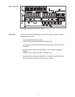
Page 28: ...e required depending on grid configuration depending on inverter type Lockable AC disconnect switch Overview Fronius IG Plus Installation and Connection contains the following sec tions Fronius IG Plu...

Page 29: ...card IG Brain 6 Open card slot for an option card 7 Open card slot for an option card 8 Plug in card NL MON Only at Fronius IG Plus 12 0 3 WYE 277 Open card slot for an option card 9 DC main switch wi...

Page 30: ...20 Item Description 12 AC side terminals 13 3 x grounding terminals 14 Strain relief for solar module strings 15 6 DC terminals 16 DC main switch Fronius IG Plus Connec tion Options continued...

Page 31: ...4 in 1 in e g for DC wire surge arrester 2 Knockout diameter 1 2 in 3 4 in only for data wires 3 Knockout diameter 3 4 in 1 in e g for AC wire surge arrester 4 Knockout diameter 1 2 in 3 4 in e g for...

Page 32: ...s required for the avai lable wire inputs CAUTION Danger of damaging the plastic base when remo ving the knockouts on the bottom Before removing remove the 3 fixing screws 6 and 7 Remove the metal ins...

Page 33: ...hoosing a location for the Fronius IG Plus Only vertical installation Max ambient temperatures 4 F 122 F 20 C 50 C Keep a distance of 8 in 20 cm minimum between each inverter or anything to the right...

Page 34: ...direct water spray such as a sprinkler be avoided if possible In order to protect the display the Fronius IG Plus should not be exposed to direct sunlight Ideally the Fronius IG Plus should be instal...

Page 35: ...for Wall Bra cket Assembly Fronius IG Plus Installation Assembling the Wall Bra cket In most cases you should use 1 4 in or 5 16 in stainless steel or alumini um screws capable of supporting 31 lbs F...

Page 36: ...ure a comfortable display height for easy reading 1 2 1 1 7 3 5 4 6 Attaching the Wall Bracket to a Concrete or Brick Wall Attaching the Wall Bracket to a Wooden Wall 9 1 1 1 2 3 4 9 2 1 2 5 Important...

Page 37: ...ked represents the placement of the inverter display Use this to ensure a comfortable display height for easy reading NOTE When installing using a metal carrier the Fronius IG Plus should not be expos...

Page 38: ...stallations must be made in accordance with the National Electrical Code ANSI NFPA 70 and any other codes and regulations applicable to the installation site For installations in Canada the installati...

Page 39: ...Plus 10 0 1 Fronius IG Plus 11 4 1 Fronius IG Plus 11 4 3 Fronius IG Plus 3 0 1 Fronius IG Plus 3 8 1 Fronius IG Plus 5 0 1 Fronius IG Plus 6 0 1 Fronius IG Plus 7 5 1 Fronius IG Plus 10 0 1 Fronius I...

Page 40: ...Plus 10 0 1 Fronius IG Plus 11 4 1 180 120 V 120 V 240 V L1 L2 N Fronius IG Plus 3 0 1 Fronius IG Plus 3 8 1 Fronius IG Plus 5 0 1 Fronius IG Plus 6 0 1 Fronius IG Plus 7 5 1 Fronius IG Plus 10 0 1 Fr...

Page 41: ...three phase systems Utilities generally allow up to 6 kVA of unbalance but check with your utility and try to balance the instal lation The connection to the grid shall be done in the following way 20...

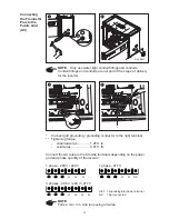
Page 42: ...3 Grid grounding Grounding conductor The Fronius IG Plus Inverter must be connected to the AC ground from the utility via the Ground Terminal NOTE Use copper wire for all grounding wires Use only soli...

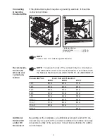
Page 43: ...fine stranded wire Fronius IG Plus AC wire AC wire AC wire 208 V 240 V 277 V 3 0 1 AWG 12 AWG 14 AWG 14 3 8 1 AWG 12 AWG 12 AWG 12 5 0 1 AWG 8 AWG 10 AWG 12 6 0 1 AWG 8 AWG 8 AWG 10 7 5 1 AWG 6 AWG 6...

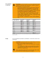
Page 44: ...r the inverter 1 2 in 3 1 Connect grid grounding grounding conductor to the right terminal Tightening torque stranded wires 1 25 ft lb solid wires 0 81 ft lb Connect the AC wires to the AC side termin...

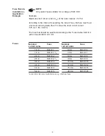
Page 45: ...1 60 A 60 A 45 A 11 4 1 70 A 60 A 60 A 11 4 3 40 A 35 A 12 0 3 20 A Connecting Grounding Electrode Wire If the photovoltaic system requires a grounding electrode it should be connected as follows NOTE...

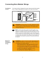
Page 46: ...o the Fronius IG Plus DC In order to select suitable solar modules and get the most efficient use out of the Fronius IG Plus please note the following points The open circuit voltage increases when te...

Page 47: ...Strings Criteria for the Proper Selection of String Fuses Connecting combined Solar Module Strings using a DC String Input Combiner Solar Module Ground at Positive Pole Connecting Solar Module Strings...

Page 48: ...a fuse in the inverter Solar Module Ground DC DC Inverter N L1 GND Solar module Solar module ground at negative pole with fuse DC main switch Wire Cross Section of Solar Module Strings WARNING An ele...

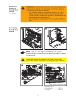
Page 49: ...er 1 3 3 1 2 in 2 4 5 4 6 4 2 1 Wire for solar module grounding Conduit WARNING An electric shock can be fatal Inadequately sized electrical components can cause serious injuries to persons and damage...

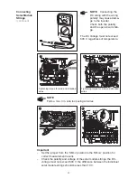
Page 50: ...1 33 ft lb NOTE Form a min 4 in wire loop using all wires 7 4 1 2 2 2 3 3 1 2 8 SMON SMOFF Important Set the jumper from the SMON position to the SMOFF position for correct measurement results Check...

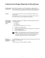
Page 51: ...eria for the Proper Selection of String Fuses max 20 A per single DC input terminal Important Follow all solar module safety instructions Follow all solar module manufacturer requirements Inserting St...

Page 52: ...manufacturers data sheet If no maximum fuse size is indicated please contact the PV module manufacturer Effects of using underra ted fuses In underrated fuses the nominal current value is less than t...

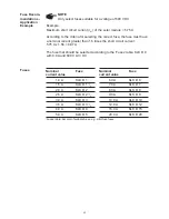
Page 53: ...circuit current 5 75 A x 1 56 8 97 A The fuse that should be selected according to the Fuses table KLK D 9 with 9 0 A and 600 V AC DC Nominal Fuse current value 1 0 A KLK D 1 1 5 A KLK D 1 1 2 2 0 A...

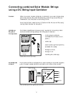
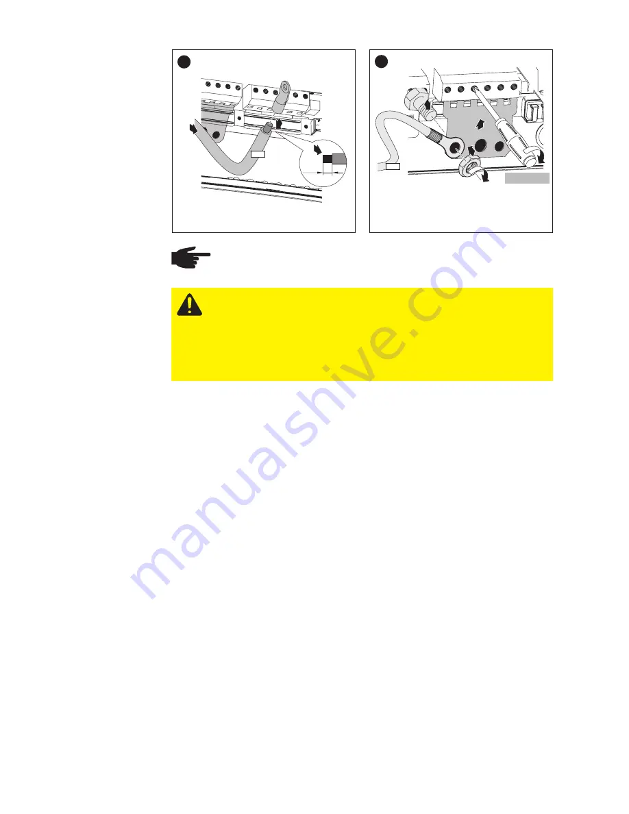
Page 54: ...sing a DC string input combiner When more solar module strings are combined to one solar module string prior to the inverter the solar module string current may exceed the per missable DC input termin...

Page 55: ...al Normally grounded conductors may be ungrounded and energized when a ground fault is indicated The ground fault has to be repaired before operation is resumed NOTE Do not connect the ground to the D...

Page 56: ...g the DC wiring with the wrong polarity may cause dama ge to the inverter Check both the polarity and the open circuit volta ge The DC Voltage must not exceed 600 V regardless of temperature Tightenin...

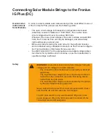
Page 57: ...ON Danger of damaging the inverter by overload Bevore starting up the inverter make sure that a conductive slug is inserted in each fuse holder for string fuses Insert conductive slugs only with a fus...

Page 58: ...the Fronius IG Plus If the DC positive is connected to ground at the DC terminal block or prior this will circumvent the GFDI protection system preventing your Fronius IG Plus from properly detecting...

Page 59: ...Module Strings continued WARNING An electric shock can be fatal Inadequately sized electrical components can cause serious injuries to persons and damage to or loss of property Use minimum AWG 14 to m...

Page 60: ...polarity and the open circuit voltage The DC Voltage must not exceed 600 V regardless of temperature NOTE Form a min 4 in wire loop using all wires Tightening torque stranded wires 1 25 ft lb solid wi...

Page 61: ...uld be less than 10 V Important The Fronius IG Plus is shipped with conductive slugs in the fuseholders Series fusing may be required depending on the type of PV module used in the system See NEC 690...

Page 62: ...sert fuses only with a fuse cover in the respective fuse holder Do not operate the Fronius IG Plus without fuse covers 1 4 2 3 2 DC DC WARNING An electrical shock can be fatal Danger from DC voltage f...

Page 63: ...manufacturers data sheet If no maximum fuse size is indicated please contact the PV module manufacturer Effects of using underra ted fuses In underrated fuses the nominal current value is less than t...

Page 64: ...circuit current 5 75 A x 1 56 8 97 A The fuse that should be selected according to the Fuses table KLK D 9 with 9 0 A and 600 V AC DC Nominal Fuse current value 1 0 A KLK D 1 1 5 A KLK D 1 1 2 2 0 A...

Page 65: ...case the DC cables can be connected to the Fronius IG Plus using a string input combiner as an option General Additional required components Option Additional Required Components 2 string input combi...

Page 66: ...current Additional ly turning the DC disconnect to the off open circuit condition will not disconnect the array from ground as it only disconnects the DC negative WARNING An electric shock can be fat...

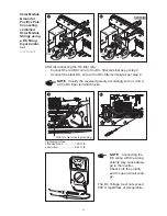
Page 67: ...r terminal as per step 4 NOTE Identify the reversed polarity accordingly with and at the DC input terminal blocks Tightening torque stranded wires 1 25 ft lb solid wires 0 81 ft lb NOTE Connecting the...

Page 68: ...tive slugs only with a fuse cover in the respec tive fuse holder Do not operate the Fronius IG Plus without fuse covers 7 2 1 2 in 1 DC 8 3 1 6x 2 3 4 DC 1 33 ft lb 9 3 1 2 in 2 1 DC 10 2 3 6x 4 3 1 D...

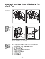
Page 69: ...for Ser vice Mainten ance Procedure for opening the Fronius IG Plus for service or maintenance 1 Disconnect the AC and DC supply from the inverter 2 Open the connection area 3 Turn off DC main switch...

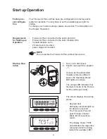
Page 70: ...vers mounted power stage set mounted NOTE Do not operate the Fronius IG Plus without fuse covers Start up Ope ration 1 off on 1 2 ON 1 Turn on AC disconnect 2 Flip DC main switch to position 1 As soon...

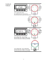
Page 71: ...product type see also section Connecting the Fronius IG Plus to the Public Grid 1 Use the Up and Down keys to select the desired grid Grid voltage 208 V Delta No neutral conductor in the system Neutra...

Page 72: ...L2 L3 Grid voltage 240 V 120 V Stinger Neutral conductor available in the system Neutral conductor monitoring is activated 2 4 0 V 2 4 0 V 1 2 0 1 2 0 120 120 V 120 V L3 L1 N L2 180 120 V 120 V 240 V...

Page 73: ...e startup phase starts again with the segment test Startup Phase at Startup Operation TESTCOM is shown Synchronization with grid WAITPS is shown The Fronius IG Plus is waiting for all power supplies i...

Page 74: ...nit starts operating Important For more information about the startup phase please see chapter Operation section Product Description Fronius IG Plus Startup Phase Test Procedure Startup Phase at Start...

Page 75: ...voltage and DC voltage from solar modules The connection area should only be opened by a licensed electrician Never work with live wires Prior to all connection work make sure that the AC and DC wire...

Page 76: ...dividers AC and DC wires are laid under the plastic dividers Make sure that the plastic dividers are present 1 1 Connecting Option Cards Laying Data Communicati on Wires CAUTION Danger of short circu...

Page 77: ...Option Cards Laying Data Communicati on Wires continued plastic dividers NOTE Only use water tight conduit fittings and conduits Conduit fittings and conduits are not part of the scope of delivery for...

Page 78: ...dinates data transmission and ensures quick and safe distribution and storage of large volumes of data The Fronius Com Card is required to integrate the Fronius IG Plus into the Solar Net Important Ev...

Page 79: ...om Card Com Card IN OUT RS 232 IN OUT Sensor Box IN OUT C W m m s PC Logging and archiving data from the inverter and sensor using a Datalog ger and sensor box Data network with 3 Fronius IG Plus unit...

Page 80: ...70...

Page 81: ...71 Operation...

Page 82: ...72...

Page 83: ...deviation of a few percent points is intrinsic to the system A calibrated meter is required to make calculations for the utility company Item Function 1 Display for displaying values settings and menu...

Page 84: ...readings that are transmitted by the energy meter optional appears with data readings that are directly related to the solar modules appears with data readings that are related to environ mental cond...

Page 85: ...Fronius IG Plus unit goes through a self test followed by an extensive test of the grid This test takes five minutes During the startup sequence the illumination of the Operating Status LED is yellow...

Page 86: ...p test takes five minutes The time elapsed is indicated by a bar shrinking from the top down Whenever two scale divisions stop flashing and disappear 1 10 of the total duration of the test is over 5 O...

Page 87: ...apter Status Diagnosis and Troubleshoo ting section The status message can be ack nowledged by pressing the Enter key lights up orange The FRONUS IG unit will enter the automatic startup phase as soon...

Page 88: ...n on the screen remains dark There is no connection to the solar modules no power output from modules due to darkness A list of most status codes the corresponding status information their status caus...

Page 89: ...oice between permanently lit or per manently dark display Activating Display Illumi nation Operating scheme the Display Accessing Menus 1 1 Press the Menu button 1 Accessing Menus Menu will appear on...

Page 90: ...display mode is shown Important The Year menu option is supported only when the optional Datalogger is connected This system upgrade includes a real time clock Example Day display mode Scrolling Betw...

Page 91: ...ield kg T CO2 reduction W maximum power output V maximum grid voltage V minimum grid voltage V maximum array voltage kwh MWh x energy as read by building load meter F C x maximum module temperature F...

Page 92: ...Display mode Year shows data for present calendar year only available in combination with optional Datalog ger Display mode Total shows data since your Fronius IG Plus unit first started operating Dis...

Page 93: ...id frequency Hertz AC current supplied current supplied to the grid at the particular moment Amperes only for a multi phase Fronius IG Plus Selecting display mode Now 1 Select display mode Now The fir...

Page 94: ...e sensor No 1 Sensor Box Datalogger and tem perature sensor required GFDI Status if there is no ground fault in the system OK GFDI is shown Power drawn from the grid opti onal present consumption Watt...

Page 95: ...t available the message N A not available is shown Time of the day optional data logger When the time on the Fronius IG Plus or a system upgrade is chan ged this changes the time on all connected devi...

Page 96: ...e re set after repeating the start up yield currency can be selected CO2 reduction lbs maximum power supplied Watts maximum grid voltage Volts minimum grid voltage Volts energy supplied kWh operating...

Page 97: ...per kWh in setup menu As was the case for the energy supplied readings may differ from those of other instruments CO2 reduction CO2 emissions avoided during monitored period lb T T tons The area for...

Page 98: ...Datalogger and consumption sensor required Maximum module temperature optional highest temperature reading at solar modules during observation period F can also be set for C in setup menu temperature...

Page 99: ...of operation of Fronius IG Plus unit HH MM Duration of operation is shown in hours and minutes up to 999 h and 59 min display 999 59 From then on only full hours are displayed Although the Fronius IG...

Page 100: ...setup menu allows easy readjustment of the Fronius IG Plus s preset parameters to your needs Default Set tings Enter the setup menu 1 2 3 4 1 Switch to the menu level press the Menu key 2 Select the...

Page 101: ...e the power supply operation into the grid is resumed automatically after completion of the startup phase the LED is illuminated green Grid supply operation can be resumed at any time whenever the LED...

Page 102: ...oicing the energy supplied Unit Display area Currency Charge rate kWh Factory setting USD CO2 setting of CO2 reduction factor Unit lb kWh or T kWh Display area 00 01 99 99 Factory setting 1 3 lb kWh Y...

Page 103: ...e Personal Display Card and Interface Card Unit Setting range Displays OKCOM PDCDRST IFCDRST Factory setting TIME setting of date and time Unit DDMMYYYY HH MM Display area Date Time Factory setting Th...

Page 104: ...Enter key the changed value is saved in the menu item 6 Press the Esc key to exit the menu item Restoring the grid feed 1 Select the menu item STANDBY 2 Press the Enter key The Fronius IG Plus will sw...

Page 105: ...Setting menu item CONTRAST 1 Select menu item CONTRAST 2 Press the Enter key Setting 7 for maximum possib le contrast is shown 3 Use the Up and Down keys to select the desired level of cont rast item...

Page 106: ...g 5 Press the Esc key to exit menu item LIGHTMODE or to maintain previous setting 1 Select menu item CASH 2 Press the Enter key The currency is shown factory setting USD The first character flashes 3...

Page 107: ...14 USD kWh The first digit flashes 10 Use the Up and Down keys to select a value for the first digit e g 0 11 Press the Enter key The second digit flashes 12 Use the Up and Down keys to select a value...

Page 108: ...e for energy supplied flashes 18 Press the Enter key The currency and the rate for supplied energy are now accep ted 19 Press the Esc key to exit menu item CASH or to maintain previous setting Setting...

Page 109: ...Down keys to select a value for the second digit after the decimal point 10 Press the Enter key The set CO2 reduction factor flashes 11 Press the Enter key The set CO2 reduction factor is now accepted...

Page 110: ...second digit 6 Press the Enter key The third digit of the OFFSET value flashes 7 Use the Up and Down keys to select a value for the third digit 8 Press the Enter key The fourth digit of the OFFSET va...

Page 111: ...key The set OFFSET value is now accepted CALI is shown 17 Press the Enter key The correction value in is shown the digit for the sign flashes 18 Use the Up and Down keys to select a sign for the corr...

Page 112: ...p and Down keys to select a value for the second digit 6 Press the Enter key The digit after the decimal point flashes 22 Use the Up and Down keys to select a value for the digit after the decimal poi...

Page 113: ...the Enter key Setting menu item DATCOM 1 Select menu item DATCOM 2 Press the Enter key The following displays depend on whether a data connection is avai lable a data connection is faulty or an option...

Page 114: ...not installed ERRORCOM is shown 3 Press the Esc key to exit menu item DATCOM Setting menu item TIME 1 Select menu item TIME 2 Press the Enter key The date is shown DD MM YYYY the first digit for the d...

Page 115: ...Press the Enter key The third digit for the year flashes 15 Use the Up and Down keys to select a value for the third year digit 16 Press the Enter key The first digit for the month flashes 7 Use the U...

Page 116: ...st digit for the minutes flashes 24 Use the Up and Down keys to select a value for the first minu tes digit 25 Press the Enter key The time is shown HH MM 0 24 h the first digit for the hour flashes 2...

Page 117: ...Y standby no grid feed 3 Press the Enter key to display the last status message saved The set time flashes 28 Press the Enter key to apply the time 29 Press the Esc key to exit menu item TIME or to ma...

Page 118: ...vailable The status of the selected power stage set is shown e g RUNPSO1 RUN active grid feed 6 Press the Enter key to display the last status message saved Displaying menu item STATEPS continued the...

Page 119: ...RL is shown 8 Press the Down key to display the power stage sets The component ID of the IG Brain unit is shown 5 Press the Down key to display the identification number of the IG Brain unit The versi...

Page 120: ...n key to display the component ID The identification number of the selected power stage set is shown 14 Press the Down key to display the hardware version of the power stage set The hardware version o...

Page 121: ...111 PS is shown 17 Press the Esc key to exit menu item VERSION The selected power stage set is shown 16 Press the Esc key Displaying menu item VERSION continued...

Page 122: ...112...

Page 123: ...113 Troubleshooting and Maintenance...

Page 124: ...114...

Page 125: ...t If it subsequently continues to operate normally there has not been a system error Displaying Status Codes Normal opera tion status codes The open circuit voltage of the solar modules is too low As...

Page 126: ...ormation can be found in The Setup Menu section STATEPS Menu item Class 1 Status Codes The first reaction of your Fronius IG Plus unit is to disconnect from the grid Subsequently the grid will be chec...

Page 127: ...s will resume feeding power into the grid Remedy Check grid connections and fuses If this status message keeps recurring contact your system installer 1x5 AC frequency too high Behavior Grid condition...

Page 128: ...ay remains at 109 e g when 2 phases report 104 and one phase 101 Behavior Grid conditions are thoroughly tested and as soon as they are again within the permissible range the Froni us IG Plus will res...

Page 129: ...ible range Fronius IG Plus resumes feeding power into the grid Remedy Check grid connections and fuses if the status code does not disappear you should contact your electrical contractor Class 3 Statu...

Page 130: ...power feeding into the grid caused by overtemperature Remedy after a two minutes cooling phase your Fronius IG Plus unit restarts Should the status code persist you should contact your electrical cont...

Page 131: ...p phase Remedy automatically Should the status code persist you should contact your electrical contractor Class 3 Status Codes continued Class 4 Status Codes Class 4 status codes may require the inter...

Page 132: ...lus disconnects from the grid for safety reasons Remedy If status code persists you should contact a Fronius trained service technician 412 The setting fixed voltage has been selected instead of the M...

Page 133: ...ia a red Ope rating Status LED Remedy If status code persists contact a Fronius trained service technician 421 PCB number has been set incorrectly Behavior The Fronius IG Plus stops feeding power into...

Page 134: ...cal error via a red Ope rating Status LED Remedy If status code persists contact a Fronius trained service technician 445 Invalid power stage set configuration Behavior The Fronius IG Plus stops feedi...

Page 135: ...cal error via a red Ope rating Status LED Remedy If status code persists contact a Fronius trained service technician 452 Communication between Guard and the digital signal processor DSP has been inte...

Page 136: ...edy If status code persists contact a Fronius trained service technician 460 Reference power source for the digital signal processor DSP is opera ting outside of tolerances Behavior The Fronius IG Plu...

Page 137: ...a start command from the IG Brain for lon ger than 6 s Behavior The Fronius IG Plus will automatically attempt to connect again and if possible resume feeding power into the grid Remedy If status code...

Page 138: ...ble Description Fronius IG Plus address issued twice Remedy change Fronius IG Plus address section The Setup Menu Description The LocalNet components required are in the Fronius IG Plus unit still com...

Page 139: ...nnot be activated because they are in boot mode Remedy Update power stage set firmware 514 No communication with one of the power stage sets Description Warning message from one of the power stage set...

Page 140: ...ective Remedy Measure string fuses and replace any that are defec tive 550 Jumper set incorrectly Description The jumper on the Print C Box was not reset to the SMON position after the solar module st...

Page 141: ...y be opened by a licensed electrician The separate power stage set area should only be discon nected from the connection area after first being discon nected from the grid power The separate power sta...

Page 142: ...n the connection area 3 Turn off DC main switch 4 Allow the capacitors to discharge 5 minutes 5 Remove metal covers 6 Remove the plastic dividers 7 Remove string fuses 8 Disconnect DC wire 9 Disconnec...

Page 143: ...and DC voltage from solar modules The connection area should only be opened by a licensed electrician Never work with live wires Prior to all connection work make sure that the AC and DC wires are no...

Page 144: ...for solar modules that meet the Criteria for the Proper Selection of String Fuses Test the fuse holder at the terminal for continuity 1 WARNING An electrical shock can be fatal Danger from DC voltage...

Page 145: ...ing Froni us IG Plus 1 1 Return plastic dividers to their proper position Important Make sure that the plastic dividers are underneath any data communication wires that are present 3 2 1 1 5 4 3 1 2 8...

Page 146: ...C and DC wires are not charged The DC main switch is only used to switch off power to the power stage set When the DC main switch is turned off the connection area is still energized These servicing i...

Page 147: ...fuses that comply with the following data for the GFDI fuse Test the fuse holder at the terminal for continuity 1 WARNING An electrical shock can be fatal Danger from DC voltage from solar modules Ne...

Page 148: ...us IG Plus Connect available data communi cation wire to the option cards Important Make sure that the plastic dividers are underneath any data communication wires that are present 3 2 1 1 5 4 3 1 2 8...

Page 149: ...139 Appendix...

Page 150: ...140...

Page 151: ...erating AC voltage range default at 208 V 183 229 V at 240 V 211 264 V at 277 V 244 305 V Adjustment range for voltage at 208 V 105 248 V at 240 V 120 287 V at 277 V 140 324 V Voltage trip limit accur...

Page 152: ...NEMA 3R Unit dimensions w x h x d 24 84 x 17 09 x 9 61 in 631 x 434 x 244 mm Inverter weight 31 lbs 14 kg Wiring compartment weight 24 lbs 11 kg Shipping dimensions w x h x d 31 02 x 20 28 x 14 02 in...

Page 153: ...g AC voltage range default at 208 V 183 229 V at 240 V 211 264 V at 277 V 244 305 V Adjustment range for voltage at 208 V 105 248 V at 240 V 120 287 V at 277 V 140 324 V Voltage trip limit accuracy 1...

Page 154: ...w x h x d 48 07 x 17 09 x 9 61 in 1221 x 434 x 244 mm Inverter weight 82 lbs 37 kg Wiring compartment weight 26 lbs 12 kg Shipping dimensions 42 72 x 20 28 x 14 02 in 17 72 x 20 28 x 14 02 in w x h x...

Page 155: ...g AC voltage range default at 208 V 183 229 V at 240 V 211 264 V at 277 V 244 305 V Adjustment range for voltage at 208 V 105 248 V at 240 V 121 287 V at 277 V 140 324 V Voltage trip limit accuracy 1...

Page 156: ...NEMA 3R Unit dimensions w x h x d 36 46 x 17 09 x 9 61 in 926 x 434 x 244 mm Inverter weight 57 lbs 4 kg Wiring compartment weight 24 bs 11 kg Shipping dimensions w x h x d 42 72 x 20 28 x 14 02 in 1...

Page 157: ...g AC voltage range default at 208 V 183 229 V at 240 V 211 264 V at 277 V 244 305 V Adjustment range for voltage at 208 V 105 248 V at 240 V 121 287 V at 277 V 140 324 V Voltage trip limit accuracy 1...

Page 158: ...NEMA 3R Unit dimensions w x h x d 36 46 x 17 09 x 9 61 in 926 x 434 x 244 mm Inverter weight 57 lbs 26 kg Wiring compartment weight 26 lbs 12 kg Shipping dimensions w x h x d 42 72 x 20 28 x 14 02 in...

Page 159: ...Operating AC voltage range default at 208 V 183 229 V at 240 V 211 264 V at 277 V 244 305 V Adjustment range for voltage at 208 V 105 248 V at 240 V 121 287 V at 277 V 140 324 V Voltage trip limit acc...

Page 160: ...NEMA 3R Unit dimensions w x h x d 36 46 x 17 09 x 9 61 in 926 x 434 x 244 mm Inverter weight 57 lbs 26 kg Wiring compartment weight 26 lbs 12 kg Shipping dimensions w x h x d 42 72 x 20 28 x 14 02 in...

Page 161: ...ng AC voltage range default at 208 V 183 229 V at 240 V 211 264 V at 277 V 244 305 V Adjustment range for voltage at 208 V 105 248 V at 240 V 121 287 V at 277 V 140 324 V Voltage trip limit accuracy 1...

Page 162: ...s w x h x d 48 07 x 17 09 x 9 61 in 1221 x 434 x 244 mm Inverter weight 82 lbs 37 kg Wiring compartment weight 26 lbs 12 kg Shipping dimensions 42 72 x 20 28 x 14 02 in 17 72 x 20 28 x 14 02 in w x h...

Page 163: ...Operating AC voltage range default at 208 V 183 229 V at 240 V 211 264 V at 277 V 244 305 V Adjustment range for voltage at 208 V 105 248 V at 240 V 121 287 V at 277 V 140 324 V Voltage trip limit acc...

Page 164: ...s w x h x d 48 07 x 17 09 x 9 61 in 1221 x 434 x 244 mm Inverter weight 82 lbs 37 kg Wiring compartment weight 26 lbs 12 kg Shipping dimensions 42 72 x 20 28 x 14 02 in 17 72 x 20 28 x 14 02 in w x h...

Page 165: ...al AC output voltage 208 V 240 V Operating AC voltage range default at 208 V 183 229 V at 240 V 211 264 V Adjustment range for voltage at 208 V 105 248 V at 240 V 121 287 V Voltage trip limit accuracy...

Page 166: ...x d 48 07 x 17 09 x 9 61 in 1221 x 434 x 244 mm Inverter weight 82 lbs 37 kg Wiring compartment weight 26 lbs 12 kg Shipping dimensions 42 72 x 20 28 x 14 02 in 17 72 x 20 28 x 14 02 in w x h x d 108...

Page 167: ...inuous output power 12000 W Nominal AC output voltage 277 V Operating AC voltage range default at 277 V 244 305 V Adjustment range for voltage at 277 V 140 324 V Voltage trip limit accuracy 1 of nomin...

Page 168: ...07 x 17 09 x 9 61 in 1221 x 434 x 244 mm Inverter weight 82 lbs 37 kg Wiring compartment weight 26 lbs 12 kg Shipping dimensions 42 72 x 20 28 x 14 02 in 17 72 x 20 28 x 14 02 in w x h x d 1085 x 515...

Page 169: ...eutral V Adjustment range for voltage 0 016 4 25 0 016 4 25 0 016 4 25 clearing time s Voltage trip limit accuracy 1 1 1 Line to Neutral of nominal value Nominal output frequency Hz 60 60 60 Operating...

Page 170: ...2003 IEEE 1547 1 ANSI IEEE C62 41 The standard measurement and safety procedures integrated into the Fronius IG Plus ensure that the power feed is immediately interrupted in the event of a grid failur...

Page 171: ...0 years from the original purchase you discover a problem caused by defects in either workmanship or materials we will see that it is either repaired or replaced Repair or replacement depends on Froni...

Page 172: ...arranty Some states do not allow the exclusion or limitation of incidental or conse quental damages This warranty gives you specific legal rights and you may also have other rights which vary from sta...

Page 173: ...Standards 0 1 2 1 3 4 3 1 4 1 Certificate of Compliance Certificate 2065918 Master Contract 203213 Project 2097497 Date Issued 2008 11 14 The US indicator adjacent to the CSA Mark signifies that the p...

Page 174: ...APPLICABLE REQUIREMENTS 5 6 3 3 7 1 2 8 1 1 2 9 5 3 6 8 1 1 2 9 1 2 7 Certificate 2065918 Master Contract 203213 Project 2097497 Date Issued 2008 11 14 DQD 507 Rev 2004 06 30...

Page 175: ...om http www fronius com USA A Fronius Worldwide www fronius com addresses Fronius USA LLC Solar Electronics Division 10421 Citation Drive Suite 1100 Brighton MI 48116 E Mail pv us fronius com http www...

Reviews: