background image

2

Safety

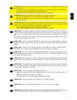
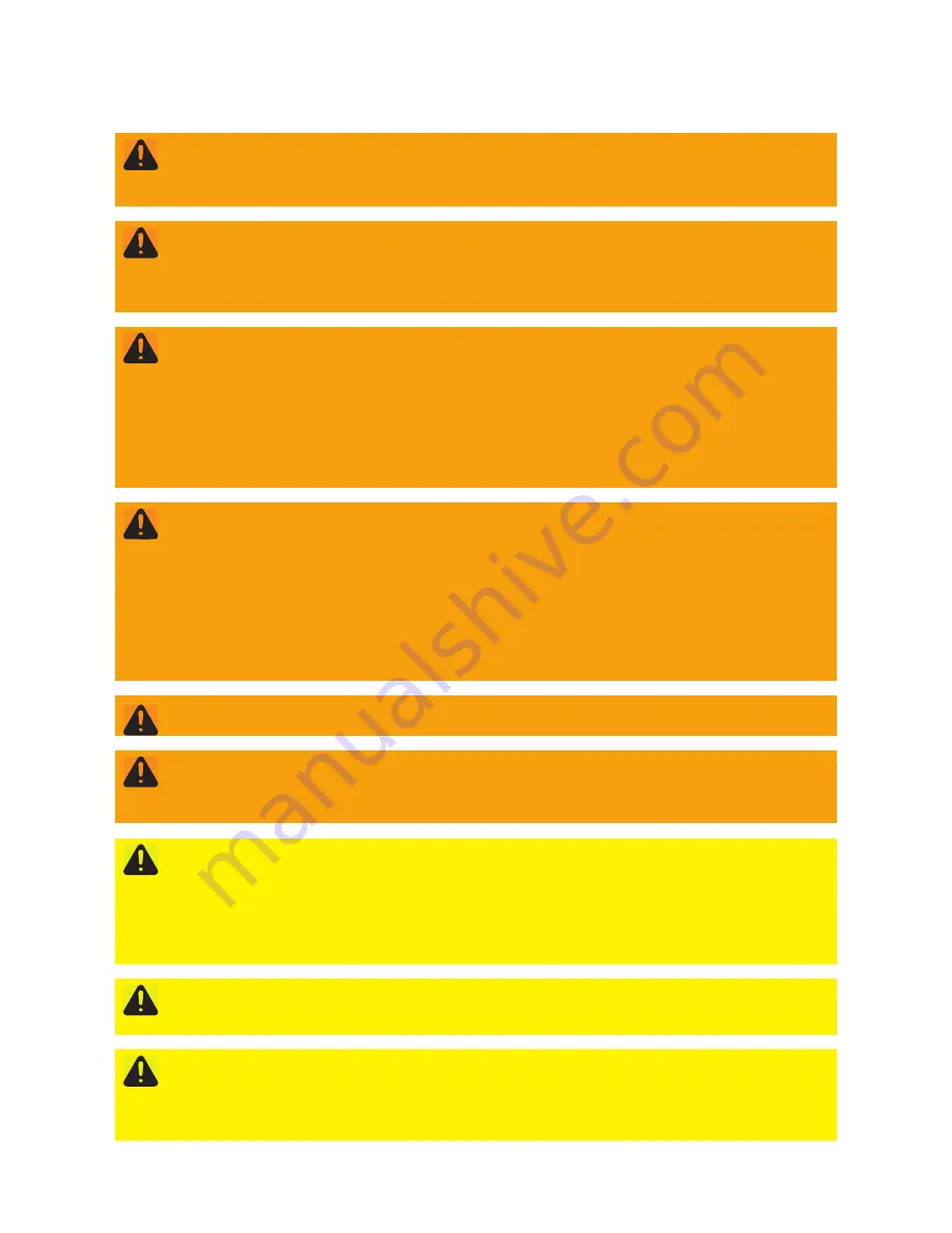
WARNING! 

Incorrect operation and work performed incorrectly can cause serious injury and damage to 

property. Only qualified staff are authorized to install your inverter and only within the scope of the res-
pective technical regulations. Do not start operation or carry out maintenance work until you have read 
the "Safety Instructions" chapter.

WARNING! 

An electric shock can be fatal. Danger due to grid voltage and DC voltage from solar modu-

les that are exposed to light.
-

Never work with live wires! Prior to all connection work, make sure that the AC and DC wires are 
not charged.

-

Only an authorised electrical engineer is permitted to connect this equipment to the public grid.

WARNING! 

An electric shock can be fatal. Inadequately sized electrical components can cause serious 

injuries to persons and damage to (or loss of) property. 
-

All electrical installations must be carried out in accordance with the National Electrical Code, ANSI/
NFPA 70, and any other codes and regulations applicable to the installation site.

-

For installations in Canada, the installations must be done in accordance with applicable Canadian 
standards.

-

Use 167 °F (75 °C), copper wire for all grounding wires (see NEC table 250.122).

-

Voltage drop and other considerations may dictate larger size wires be used.

-

Use only solid or stranded wire. Do not use fine stranded wire.

WARNING! 

An electric shock can be fatal. Danger due to grid voltage and DC voltage from solar modu-

les that are exposed to light.
-

The DC main switch is used only to switch off power to the power stage set. When the DC main 
switch is turned off, the connection area is still energized. 

-

All maintenance and service work should only be carried out when the power stage set has been 
disconnected from the connection area.

-

The separate power stage set area should only be disconnected from the connection area after first 
being disconnected from the grid power.

-

Maintenance and service work on the inverter power stage set should only be carried out by Froni-
us-trained personnel.

WARNING! 

An electric shock can be fatal. Danger from residual voltage from capacitors. You must wait 

until the capacitors have discharged. Discharge takes 5 minutes.

WARNING! 

An inadequate grounding conductor connection can cause serious injuries to persons and 

damage to (or loss of) property. The housing screws provide an adequate protective conductor connec-
tion for grounding the housing and should not be replaced under any circumstances by other screws that 
do not provide a proper protective conductor connection!

CAUTION! 

The inverter can be damaged by soiling or water on the terminals and contacts of the connec-

tion area.
-

When drilling, make sure that terminals and contacts in the connection area do not become soiled 
or wet.

-

The wall bracket without the power stage set does not possess the same degree of protection of the 
inverter as a whole and, therefore, should not be assembled without a power stage set. 
Protect the wall bracket against soiling and moisture during installation.

CAUTION! 

Danger of damaging the inverter due to improperly connected terminals. Improperly connec-

ted terminals can cause thermal damage to the inverter and may cause a fire. When connecting the AC 
and DC cables, make sure that all terminals are tightened securely using the proper torque.

CAUTION! 

Risk of fire due to incorrectly designed AC fuse. 

To reduce the risk of fire:
-

connect only to a circuit provided with branch circuit overcurrent protection in accordance with the 
National Electrical Code, ANSI / NFPA 70;

-

observe maximum values for branch circuit overcurrent protection.

Summary of Contents for Primo 208

Page 1: ... Perfect Charging Perfect Welding Solar Energy 42 0410 2115 006 09122014 Fronius Primo 208 240 Installation ...

Page 2: ...0 ...

Page 3: ...international safety requirements but as with all electrical and electronic equipment certain precautions must be observed when in stalling and or operating the inverter To reduce the risk of personal injury and to ensure the safe installation and operation of the inverter you must carefully read and follow all instructions and safety instructions in these operating instructions Failure to follow ...

Page 4: ... the power stage set has been disconnected from the connection area The separate power stage set area should only be disconnected from the connection area after first being disconnected from the grid power Maintenance and service work on the inverter power stage set should only be carried out by Froni us trained personnel WARNING An electric shock can be fatal Danger from residual voltage from cap...

Page 5: ... inverter should not be exposed to rainwater or water spray at the back Ensure proper rainwater or spray water protection NOTE When installing outdoors only use waterproof conduit fittings and conduits Conduit fittings and conduits are not part of the scope of supply for the inverter NOTE If the neutral conductor is too small it can adversely affect the inverter s feed in of power to the mains The...

Page 6: ...ad cables Check cables for damage and verify that they are laid correctly Take note of the safety instructions operating instructions and any local connection regulations Using fastening screws always screw the inverter firmly to the wall bracket to the torque specified in the operating instructions Ensure that the fastening screws are tight before starting the inver ter 3 2 2 Nm 1 Manufacturer s ...

Page 7: ...t sécurisés du l onduleur vous devez lire avec attention les pré sentes Instructions de service et suivre toutes les prescriptions et consignes de sécurité Sécurité Le chapitre suivant Sécurité contient différents avertissements Un avertissement décrit un danger pour les personnes ou les appareils Un avertissement attire l attention sur des procédures et des modalités qui si elles ne sont pas corr...

Page 8: ...teur principal DC est déconnecté la zone de raccordement reste sous tension Les opérations de maintenance et de service ne doivent être exécutées que lorsque l étage de pu issance et la zone de raccordement sont séparés Le bloc indépendant de l étage de puissance ne doit être séparé de la zone de raccordement que si l ensemble est hors tension Les opérations de maintenance et de service dans l éta...

Page 9: ...de protection NEMA4X est valable uniquement lorsque l onduleur est accroché et fermement vissé au support mural Un support mural sans onduleur ne présente aucune protection NEMA REMARQUE Respecter les consignes suivantes en cas d utilisation d entrées de câble à l arrière étanchéifier selon l indice de protection NEMA4X avant toute utilisation en extérieur REMARQUE En cas de montage sur des suppor...

Page 10: ... installati on etc résultant de la détection d un arc électrique et de ses conséquences Fronius décline toute responsabilité en cas de survenance d incendie malgré la détection l interruption d arc électrique intégrée par ex du fait d un arc électrique parallèle REMARQUE Avant de réinitialiser l onduleur après la détection d un arc électrique contrôler l état de l ensemble de l installation photov...

Page 11: ...service y compris les bornes de mise à la terre libres Ne surchargez pas les câbles Vérifiez les éventuels dommages sur les câbles ainsi que la cor rection du montage Respectez les consignes de sécurité les Instructions de service ainsi que les directives de connexions locales Vissez toujours l onduleur au support mural à l aide des vis de fixa tion en respectant le couple de serrage figurant dans...

Page 12: ...10 ...

Page 13: ... una in stalación y un servicio seguros del inversor es necesario leer detenidamente este manual de instrucciones y seguir todas las instrucciones e indicaciones de seguridad Seguridad El siguiente apartado Seguridad incluye diferentes advertencias Una advertencia de scribe un peligro para las personas o los aparatos Una advertencia advierte sobre proce dimientos y procesos cuya realización incorr...

Page 14: ...sin corriente Si el interruptor principal CC está desconectado la zona de conexión sigue estando bajo tensión Las actividades de mantenimiento y servicio solo deben ser realizadas cuando se hayan separado entre sí la etapa de potencia de la zona de conexión La zona separada de la etapa de potencia solo se puede separar de la zona de conexión cuando no tiene tensión Las actividades de mantenimiento...

Page 15: ...e cuando el inversor está en ganchado en el soporte mural y firmemente atornillado al mismo El soporte mural sin inversor no dispone de protección NEMA OBSERVACIÓN En caso de utilizar las entradas de cables en el lado posterior debe tenerse en cu enta lo siguiente impermeabilizar hasta conseguir el tipo de protección NEMA4X antes de servicio en el exterior OBSERVACIÓN En caso de montaje en soporte...

Page 16: ...etección de un arco voltaico y sus consecuencias Fronius no asume ninguna responsabilidad por el fuego o los incendios que puedan producirse a pesar de disponer de una detección interrupción de arco voltaico integrada por ejemplo debido a un arco voltaico paralelo OBSERVACIÓN Antes de resetear el inversor después de haber detectado un arco voltaico com probar toda la instalación fotovoltaica afect...

Page 17: ... de instrucciones incluyendo los bor nes de conexión a tierra libres No sobrecargar los cables Comprobar los cables respecto a daños y su tendido correcto Tener en cuenta las indicaciones de seguridad el manual de in strucciones así como las disposiciones de conexión locales Atornillar el inversor siempre mediante los tornillos de fijación según el par indicado en el manual de instrucciones firmem...

Page 18: ...ronius Primo 208 240 Installation Help English US Français Español English US www fronius com QR link 4204260197EA Français www fronius com QR link 4204260197FR Español www fronius com QR link 4204260197ES ...

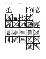
Page 19: ...17 Fronius Primo 208 240 Installation NEMA4X max 13123 ft 4000 m 13123 ft 4000 m NH3 ...

Page 20: ...18 1 1 8 in 200 mm 4 in 100 mm 6 in 150 mm 40 F 131 F 40 C 55 C 0 100 AC AC AC DC DC DC DATCOM DATCOM Installation example of several inverters 1 ON OFF Lock 2 ...

Page 21: ...19 1 1 1 EN US brick concrete wall FR mur de briques beton ES pared de ladrillo muro de hormigón NO NEMA ENCLOSURE TYPE 1 2 Al St 0 2 0 3 in 6 8 mm 3 ...

Page 22: ...20 1 EN US wooden wall FR mur en bois ES pared de madera NO NEMA ENCLOSURE TYPE 1 2 Al St 0 2 0 3 in 6 8 mm min 2x 1 ...

Page 23: ...21 1 EN US Mounting to a metal carrier FR Montage sur un support métallique ES Montaje en un soporte de metal 1 ...

Page 24: ...22 1 EN US mast pole pile FR mât pile barre ES mástil pilla barra Fronius Primo 208 240 Installation Help 1 ...

Page 25: ... mm 1 2 in 12 7 mm 3 4 in 19 05 mm 3 4 in 19 05 mm 3 4 in 19 05 mm 1 2 in 12 7 mm 1 2 in 12 7 mm 3 4 in 19 05 mm 1 2 in DATCOM 3 4 in AC DC Grounding Electrode Terminal GET METAL KNOCKOUTS Remove knockout parts fallen into the connection area before hanging the inverter to the wall bracket ...

Page 26: ...ailable 240 V Delta Corner Grounded Setup 240 No neutral conductor 240 V 120 V Stinger Setup 240N Neutral conductor available 1 2 0 1 2 0 120 2 0 8 V 2 0 8 V 208 V L1 L2 L3 120 V 120 V 120 V 1 2 0 1 2 0 120 2 0 8 V 2 0 8 V 208 V L1 L2 N L3 1 2 0 1 2 0 120 2 2 0 V 2 2 0 V 220 V L1 L2 L3 127 V 127 V 127 V 1 2 0 1 2 0 120 2 2 0 V 2 2 0 V 220 V L1 L2 N L3 2 4 0 V 2 4 0 V 240 V 1 2 0 1 2 0 120 L1 L2 L3...

Page 27: ...ded phase must be connected to the L2 terminal in the AC connection area of the inverter IMPORTANT La phase de mise à la terre doit être rac cordée à la borne de raccorde ment L2 et à la zone de raccordement AC de l onduleur IMPORTANTE La fase conec tada a tierra debe conectarse al borne L2 en la zona de conexión CA del inversor ...

Page 28: ... Energy meter AC distribution panel DC disconnect DC terminal block DC DC PV frame ground L1 L2 N Grounding terminal Grounding electrode terminal L1 N L2 Main grounding system Lockable AC disconnect switch optional Ungrounded solar modules MPPT2 MPPT1 Cu Al Cu max Class 4 DC DC AC DC Disconnect Cu min AWG 14 max AWG 6 Al AWG 6 15 93 lb in 1 33 ft lb 1 8 Nm Sense MPPT1 MPPT2 ...

Page 29: ...10 AWG Copper CU stranded and stranded Copper CU stranded and solid 10AWG and 12 AWG Copper CU stranded and stranded Copper CU solid and solid 10AWG and 14 AWG Copper CU stranded and stranded Copper CU solid and solid 12AWG and 12 AWG Copper CU stranded and stranded Copper CU solid and solid 12AWG and 14 AWG Copper CU stranded and stranded Copper CU solid and solid 14AWG and 14AWG Copper CU strand...

Page 30: ...00 mm GND L1 N L2 GND 1 5x wire loop min 4 in 101 6 mm 15 93 lb in 1 33 ft lb 1 8 Nm Sense main grounding terminal grounding terminals e g for grounding electrode PV frame grounding for connection of the grounded phase in corner grounded grids 2 AC max 63 A ...

Page 31: ...29 DC 1 1 1 DC 1 2 1 DC DC 2 1 15 mm 0 6 in 2 2x 15 93 lb in 1 33 ft lb 1 8 Nm wire loop min 4 in 101 6 mm 1 DC DC 1 1 2 2 3 ...

Page 32: ...t 0 2000 m 8202 9842 ft 2500 3000 m 6561 8202 ft 2000 2500 m 9842 11482 ft 3000 3500 m ft m 540 V 480 V 430 V 5 DC 2 DC DC 1 max 18 A per MPPT PV 1 PV 2 1 2 1 2 3 4 1 2 DC 1 DC 2 DC 1 DC 2 PV 1 PV 2 1 DC 1 DC 1 DC 2 DC 1 1 2 3 4 2 2 D1 D1 DC 1 max 36 A to a single DC terminal PV 1 1 DC 1 DC 1 DC 2 DC 1 1 2 3 4 2 2 D1 D1 DC 1 max 36 A to a single DC terminal WHEN ONLY ONE STRING IS USED ...

Page 33: ... topology Just one suitable cable is enough to provide communication between one or more inverter connected to Fronius Solar Net and a system add on Different system add ons are automatically recognized by Fronius Solar Net In order to distinguish between several identical system add ons each one must be as signed a unique number In order to clearly define each inverter in Fronius Solar Net each i...

Page 34: ...r Net LED indicates whether the Fronius Solar Net power supply is available The Solar Net LED is on the power supply for data communication within the Fronius Solar Net interface protocol is OK The Solar Net LED flashes briefly every 5 seconds data communication error in the Fronius Solar Net Overcurrent current flow 3 A e g resulting from a short circuit in the Fro nius Solar Net ring Undervoltag...

Page 35: ...ta logger Only one Fronius Datamanager per Fronius Solar Net ring 6 USB A socket for connecting a USB stick with maximum dimensions of 65 x 30 mm The USB stick can function as a datalogger for an inverter The USB stick is not included in the scope of supply of the inverter 7 Floating switch contact with mating connector max 250 V AC 4 A AC max 30 V DC 1 A DC max AWG16 1 5 mm cable cross section Pi...

Page 36: ...agers must be removed and the unoccupied option card com partment sealed off using the blanking cover 42 0405 2020 available from Fronius as an optional extra alternatively use an inverter without Fronius Datamanager light version ...

Page 37: ...s reliés dans le Fronius Solar Net puissent communiquer avec une exten sion de système un câble adapté suffit Diverses extensions de système sont automatiquement reconnues par Fronius Solar Net Pour différencier plusieurs extensions de système identiques il est nécessaire de leur at tribuer un numéro individuel Pour définir chaque onduleur de manière univoque dans Solar Net il faut également leur ...

Page 38: ...hable Fronius Datamanager 4 DEL Solar Net indique si l alimentation Solar Net est disponible La DEL Solar Net est allumée l alimentation électrique pour la communication de données au sein du Fronius Solar Net Interface Protocol fonctionne correctement La DEL Solar Net clignote brièvement toutes les 5 secondes erreur dans la communication de données dans le Fronius Solar Net Surintensité flux de c...

Page 39: ...e retirée 6 Connecteur USB A pour le raccordement d une clé USB de taille maximale 65 x 30 mm La clé USB peut jouer un rôle de datalogger pour un onduleur La clé USB n est pas comprise dans la livraison de l onduleur 7 Contact sans potentiel avec contre fiche max 250 V AC 4 A AC max 30 V DC 1 A DC section de câble max AWG16 1 5 mm Broche 1 contact à ouverture Normally Closed Broche 2 passe de fond...

Page 40: ...ans le circuit Fronius Solar Net Un seul Fronius Datamanager par circuit Fronius Solar Net Démonter tous les autres Fronius Datamanager et obturer le compartiment pour cartes d option libre au moyen du cache disponible en option auprès de Fronius 42 0405 2020 ou utiliser un onduleur sans Fronius Datamanager version light ...

Page 41: ...cación de uno o varios inversores conectados en Fronius Solar Net con una extensión del sis tema basta con un cable adecuado Fronius Solar Net detecta automáticamente las diferentes extensiones del sistema Para poder diferenciar entre varias extensiones del sistema idénticas es necesario ajustar un número individual en las extensiones del sistema Para definir cada inversor de manera unívoca en Fro...

Page 42: ...yen 2 clavijas finales en el volumen de suministro del inversor 4 LED Solar Net Indica si la alimentación principal de Fronius Solar Net se encuentra a disposi ción El LED Solar Net está iluminado La alimentación principal para la comunicación de datos dentro de Fronius Solar Net del protocolo de interfaz está en orden El LED Solar Net parpadea brevemente cada 5 segundos Error en la comunicación d...

Page 43: ... mm La memoria USB puede funcionar como un Datalogger para un inversor La me moria USB no forma parte del volumen de suministro del inversor 7 Contacto de conmutación libre de potencial con conector opuesto máx 250 V CA 4 A CA máx 30 V CC 1 A CC máx AWG16 1 5 mm de sección transversal de cable Pin 1 Contacto de apertura normalmente cerrado Pin 2 Posición de la raíz común Pin 3 Contacto de cierre n...

Page 44: ...Fronius Solar Net Solo un Fronius Datamanager por cada circuito de Fronius Solar Net Desmontar los demás Fronius Datamanager y cerrar el compartimento de tarjetas opcio nales libre con la cubierta ciega disponible como opción a través de Fronius 42 0405 2020 o utilizar un inversor sin Fronius Datamanager versión light ...

Page 45: ...43 DATCOM 1 1 1 1 4 x TX25 2 3 4 1 5 1 1 2 1 3 TX20 10 62 lb in 0 89 ft lb 1 2 Nm 1 2 4 ...

Page 46: ...44 1 1 1 1 1 1 1 5 6 3 1 4 5 2 5 22 13 lb in 1 84 ft lb 2 5 Nm 4 x TX25 7 2 1 8 1 1 1 2x 42 0405 2019 1 1 9 1 2 3 4 5 6 10 ...

Page 47: ...45 1 1 1 1 42 0405 2019 1 CLICK 2 TOP 11 1 1 1 2 3 4 33 in 110 mm 12 2 ON OFF Lock 22 13 lb in 1 84 ft lb 2 5 Nm 1 4 3 5 NO CABLE LOOP 2 x TX25 13 IN OUT IN OUT 1 3 2 4 14 ...

Page 48: ... 1 1 2 3 4 22 13 lb in 1 84 ft lb 2 5 Nm 2 AC ON 2 ON OFF Lock 1 3 1 1 Setups 240N 240 208N 208 220N 220 50HZ 50 HN 1 1 1 6 2 6 1 4 i n s t E X V 0 0 0 3 0 x 0 0 0 1 n e w 240N V 0 0 0 1 0 x 0 0 0 1 C o u n t r y C O N F I G 2 1 5 C O N F I G L o a d i n g C o u n t r y S e t u p 6 7 2 1 6x 7x 8 ...

Page 49: ...47 1 1 1 1 1 2 1 4x 5x 9 S E T U P A u t o D a y l i g h t s a v i n g 2 1 10 2 1 B A S I C M P P T R A C K E R 2 11 12 13 ...

Page 50: ...t of the scope of delivery for the inverter FR Le cadenas n est pas compris dans la livraison de l on duleur ES El candado no está parte del volumen de suministro del inversor 2 2 1 TX25 1 2 22 13 lb in 1 84 ft lb 2 5 Nm 3 1 TX25 2 2 2 1 max 0 28 in 7 mm 3 ...

Page 51: ...is not part of the scope of delivery for the inverter FR Le cadenas n est pas compris dans la livraison de l on duleur ES El candado no está parte del volumen de suministro del inversor 1 1 1 max 0 28 in 7 mm 2 1 1 max 0 28 in 7 mm 3 ...

Page 52: ...ce technicians or Fronius service provider FR IMPORTANT Le micrologiciel ne peut être mis à jour que par des techniciens ou des partenaires du service commercial Fronius ES IMPORTANTE Actualización de firmware solo a través de un técnico o Fronius Service Provider 5 4 4 USB 3 1 2 2 ...

Page 53: ...racker 1 MPP Tracker 2 USB Eventlog Input signal SMS Relay Insulation Settings Temperature Warning TOTAL Reset 6x 6 1 5x 1 2 5x 2 1 3 M P P T r a c k e r 1 M P P T r a c k e r 2 U S B E v e n t l o g I n p u t S i g n a l S M S R e l a y 4 ...

Page 54: ...e 218 288 0 016 4 25 1 255 231 288 0 016 4 25 1 255 UOmin adjustable 104 198 0 016 4 25 1 255 104 209 0 016 4 25 1 255 Setup 240 V Setup 50HZ UAC V Clearing Time s Clearing Time cyl UAC V Clearing Time s Clearing Time cyl U 50 120 0 16 9 110 0 16 8 50 U 88 211 2 118 194 2 100 110 U 120 264 1 58 242 1 50 U 120 288 0 16 9 264 0 16 8 UImin adjustable 104 228 0 016 4 25 1 255 104 209 0 016 21 0 1 1050...

Page 55: ...l 60 Hz setups Frequency for all 50 Hz setups F Hz Clearing Time s Clearing Time cyl F Hz Clearing Time s Clearing Time cyl FImax 0 5 60 5 0 16 9 50 5 0 16 8 FOmax 2 0 62 0 0 16 9 55 0 0 16 8 FImin 0 7 59 3 0 16 9 48 0 0 16 8 FOmin 3 0 57 0 0 16 9 45 0 0 16 8 FImin adjustable 50 00 65 00 0 016 600 1 36000 45 00 55 00 0 016 600 1 30000 FImax adjustable 50 00 65 00 0 016 600 1 36000 45 00 55 00 0 01...

Page 56: ... AC Voltage s Unit Seconds cyl Unit Cycles 1 UImin U Inner Limit min min inner limit voltage UImax U Inner Limit max max inner limit voltage UOmin U Outer Limit min min outer limit voltage UOmax U Outer Limit max max outer limit voltage Unom nominal Voltage FImin F Inner Limit min min inner limit frequency FImax F Inner Limit max max inner limit frequency FOmin F Outer Limit min min outer limit fr...

Page 57: ...canada fronius com http www fronius ca Tel 1 905 288 2100 Fax 1 905 288 2101 Fronius Mexico S A de C V Carretera Monterrey Saltillo 3279 E Parque Landus Business Park Santa Catarina NL 66367 México E Mail ventas mexico fronius com http www fronius mx Tel 52 81 88828200 Fax 52 81 88828201 Fronius International GmbH Froniusplatz 1 4600 Wels Austria E Mail pv sales fronius com http www fronius com Un...

Page 58: ......

Page 59: ......
Page 60: ...nd all addresses of our sales branches and partner firms Fronius International GmbH 4600 Wels Froniusplatz 1 Austria E Mail pv sales fronius com http www fronius com Fronius USA LLC Solar Electronics Division 6797 Fronius Drive Portage IN 46368 E Mail pv us fronius com http www fronius usa com ...

Reviews: