115
EN
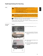
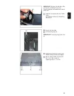
IMPORTANT!
The sealing foam will only be
positioned correctly and create an effective
seal if the procedure a) - b) below is follo-
wed.
Attach the power stage set cover to the
fastener at the top and, while keeping
the power stage set cover at an angle,
pull it downwards a) and - under tensi-
on - pivot it onto the base shell b).
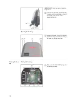
IMPORTANT!
When closing the cover,
make sure that the springs on the keys en-
gage in the guides.
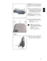
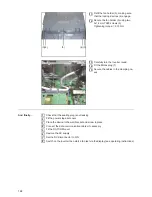
Secure the power stage set cover (3)
using four 5x18 mm TX25 screws (2)
with seal rings
Tightening torque = 2.5 Nm
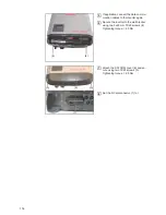
Installation
Attach the inverter to the wall bracket
at the top at a maximum angle of 11°
and push it towards the wall bracket
a)
b)
2
(2) (2)
(2)(2)
(3)
NOTE!
If the thread of these
screws is rotating and the screws
no longer engage, use the follow-
ing screws:
PT 5x25 mm T25 KT25
(item number 42,0401,4231)
3
4.33 in.
110 mm
max. 11°
4
Summary of Contents for Primo 3.0-1
Page 2: ...2 ...
Page 5: ...Allgemeine Informationen ...
Page 6: ......
Page 13: ...Fehler Suchhilfe ...
Page 14: ......
Page 32: ...32 ...
Page 33: ...Komponenten austauschen ...
Page 34: ......
Page 54: ...54 DC Trenner auf ON stellen 6 ...
Page 65: ...Sicherheitstechnische Überprüfung ...
Page 66: ......
Page 78: ...78 ...
Page 81: ...General information ...
Page 82: ......
Page 89: ...Error location aid ...
Page 90: ......
Page 108: ...108 ...
Page 109: ...Changing components ...
Page 110: ......
Page 130: ...130 Set the DC disconnector to ON 6 ...
Page 141: ...Safety Inspections ...
Page 142: ......
Page 154: ...154 ...
Page 155: ...Appendix ...
Page 158: ...158 ...
Page 159: ...159 ...

