118
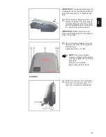
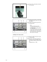
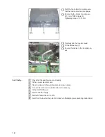
Remove the control switch with shaft
(2) downwards
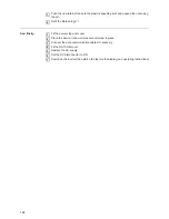
Remove the four 4x9 mm TX20 screws
(3) and take the disconnector out of the
wall bracket.
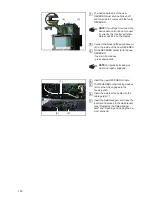
Remove the hidden fuse (4) from the
DC disconnector
*
Note:
the strain-relief device is still
connected to the DC disconnector
in the illustration.
The strain-relief device can be loo-
sened to disconnect the AC and DC
cables and must be removed from
the DC disconnector when the DC
disconnector is removed.
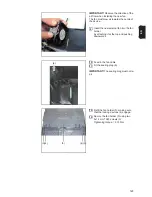
Installing the DC disconnector:
Attach the hidden fuse (4) to the new
DC disconnector
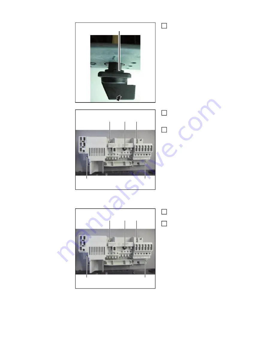
Place the new DC disconnector with
hidden fuse in the wall bracket and se-
cure using four 4x9 mm TX20 screws
(3)
Tightening torque = 2 Nm
2
(2)
2
(3)
(3)
(3)
(3)
(4)
*
3
4
(3)
(3)
(3)
(3)
(4)
*
1
2
Summary of Contents for Primo 3.0-1
Page 2: ...2 ...
Page 5: ...Allgemeine Informationen ...
Page 6: ......
Page 13: ...Fehler Suchhilfe ...
Page 14: ......
Page 32: ...32 ...
Page 33: ...Komponenten austauschen ...
Page 34: ......
Page 54: ...54 DC Trenner auf ON stellen 6 ...
Page 65: ...Sicherheitstechnische Überprüfung ...
Page 66: ......
Page 78: ...78 ...
Page 81: ...General information ...
Page 82: ......
Page 89: ...Error location aid ...
Page 90: ......
Page 108: ...108 ...
Page 109: ...Changing components ...
Page 110: ......
Page 130: ...130 Set the DC disconnector to ON 6 ...
Page 141: ...Safety Inspections ...
Page 142: ......
Page 154: ...154 ...
Page 155: ...Appendix ...
Page 158: ...158 ...
Page 159: ...159 ...


