138
IMPORTANT
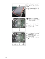
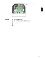
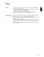
! When inserting the new PC
board, ensure that the heat-conducting
paste on the modules (9) is not scratched or
removed.
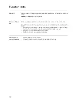
Place the new PC board on the heat
sink
Screw the modules onto the heat sink
using four 4x9 mm TX20 screws (6).
Tightening torque = 0.5 Nm
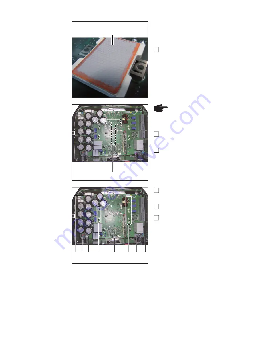
Retighten the four 4 x 9 mm TX20
screws (6) to 2.0 Nm.
Screw the PrimoPS PC board into pla-
ce using 14 4x9 mm TX20 screws (5)
Tightening torque = 2 Nm
Reconnect all the cables (2) - (4) to the
PrimoPS PC board
Feed the LVRT cable into the ferrite
ring
(9)
3
(6)
NOTE!
To avoid mechanical
stress, first tighten the screws with
a tightening torque of 0.5 Nm, then
retighten to 2.0 Nm.
4
5
(2)
(3)
(4) (5)
(5)
(5)
(5)
(5)
6
7
8
Summary of Contents for Primo 3.0-1
Page 2: ...2 ...
Page 5: ...Allgemeine Informationen ...
Page 6: ......
Page 13: ...Fehler Suchhilfe ...
Page 14: ......
Page 32: ...32 ...
Page 33: ...Komponenten austauschen ...
Page 34: ......
Page 54: ...54 DC Trenner auf ON stellen 6 ...
Page 65: ...Sicherheitstechnische Überprüfung ...
Page 66: ......
Page 78: ...78 ...
Page 81: ...General information ...
Page 82: ......
Page 89: ...Error location aid ...
Page 90: ......
Page 108: ...108 ...
Page 109: ...Changing components ...
Page 110: ......
Page 130: ...130 Set the DC disconnector to ON 6 ...
Page 141: ...Safety Inspections ...
Page 142: ......
Page 154: ...154 ...
Page 155: ...Appendix ...
Page 158: ...158 ...
Page 159: ...159 ...


