151
EN
Finally...
General
-
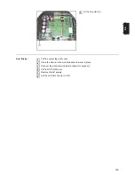
Disconnect the inverter from the AC grid and DC supply when it is not under load (set
the DC disconnector to position 0).
-
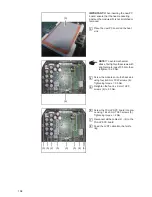
Re-attach/connect all the Datcom leads that were removed (restore the inverter to the
state it was in before the repair or safety inspection).
-
If necessary, replace the AC lead in the PG gland.
-
Check whether any conductive objects have been placed in the housing.
-
Fit the Datcom cover using four 5x16 TX25 screws -
2 Nm
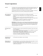
Visual inspection
Any defects that could cause other hazards must be rectified immediately or restrictions
placed on the further use of the system until repairs have been effected.
-
Missing or damaged housing components, insulation components or protective cov-
ers.
-
Dirt or blockages in cooling openings.
-
Check that all safety-related labels (e.g. warning notices, grounding symbols, rating
plates, etc.) are present. If required, replace, supplement or amend them as appropri-
ate.
-
Ensure that all safety-related labels or symbols, measurement data and positioning in-
dicators are legible.
Summary of Contents for Primo 3.0-1
Page 2: ...2 ...
Page 5: ...Allgemeine Informationen ...
Page 6: ......
Page 13: ...Fehler Suchhilfe ...
Page 14: ......
Page 32: ...32 ...
Page 33: ...Komponenten austauschen ...
Page 34: ......
Page 54: ...54 DC Trenner auf ON stellen 6 ...
Page 65: ...Sicherheitstechnische Überprüfung ...
Page 66: ......
Page 78: ...78 ...
Page 81: ...General information ...
Page 82: ......
Page 89: ...Error location aid ...
Page 90: ......
Page 108: ...108 ...
Page 109: ...Changing components ...
Page 110: ......
Page 130: ...130 Set the DC disconnector to ON 6 ...
Page 141: ...Safety Inspections ...
Page 142: ......
Page 154: ...154 ...
Page 155: ...Appendix ...
Page 158: ...158 ...
Page 159: ...159 ...


