I 35
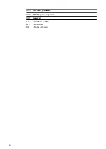
Reserved
36
Reserved
37
NC
TC
= Robacta TC 2000
WC
= wire cutter
RR
= Robacta Reamer
Optional Connec-
tions Robot Con-
trol Unit (Field-
bus)
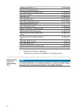
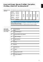
If the welding torch service station is equipped with an optional fieldbus as a robot con-
trol unit connection, then the connection is described in the separate Operating Instruc-
tions for the fieldbus:
42,0410,2245 ... ProfiNet Robacta TSS /i
42,0410,2434 … DeviceNet Robacta TSS /i
42,0410,2435 … ProfiBus Robacta TSS /i
42,0410,2436 … EtherCAT Robacta TSS /i
42,0410,2550 ... Ethernet IP Robacta TSS/i
Assignment of
external optional
equipment con-
nection
CAUTION!
Danger from overcurrent.
Damage to the bearings may result.
▶
Provide the power supply with 1.5 A fuse protection against overcurrent.
NOTE!
To avoid interference, keep the line length between the welding torch service sta-
tion and the robot control unit as short as possible.
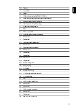
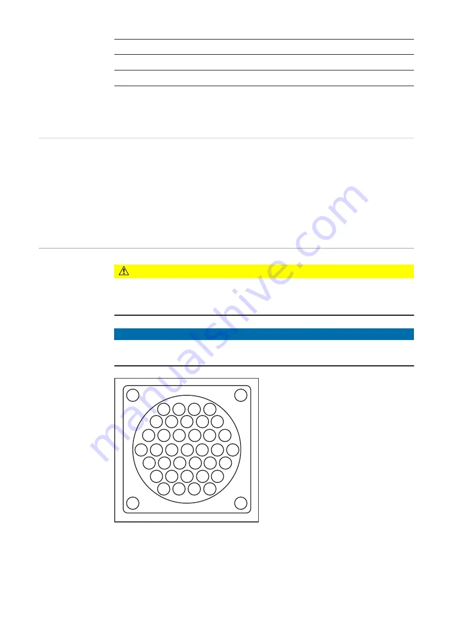
1
2
3
4
9
8
7
6
5
10
11
12
13
14
15
22 21 20 19 18 17 16
28 27 26 25 24 23
33 32 31 30 29
37 36 35 34
I = Input:
from the optional equipment to the welding
torch service station
O = Output:
from the welding torch service station to
the optional equipment
26
Summary of Contents for Robacta TSS /i
Page 2: ......
Page 11: ...General 11 ...
Page 12: ...12 ...
Page 18: ...18 ...
Page 19: ...Operating controls connections and mechanical components 19 ...
Page 20: ...20 ...
Page 32: ...32 ...
Page 33: ...Installation and Startup 33 ...
Page 34: ...34 ...
Page 61: ...12 12 12 Connect the compressed air supply 61 EN US ...
Page 64: ...64 ...
Page 65: ...Cleaning Program Sequence 65 ...
Page 66: ...66 ...
Page 68: ...A B C D E F G 68 ...
Page 79: ...Reset external signal Internal valve brush cleaning 79 EN US ...
Page 84: ...Reset external signal Cut wire electrode End of the cleaning process Welding 84 ...
Page 85: ...Troubleshooting Maintenance and Disposal 85 ...
Page 86: ...86 ...
Page 97: ...Appendix 97 ...
Page 98: ...98 ...


