background image

2

Protection of personnel

Housing

Galvanic (elec-
trical) isolati-
on

The inverter connection compartment must only be opened by an autho-
rised installation engineer.

Never open the connection compartment when the power is connected.

The separate power module housing must only be opened by a trained
Fronius service technician and only when in a de-energised state.

The design and operation of the inverter ensures maximum safety when
installing the Fronius Signal Card. The DC and AC sides are fully galvani-
cally (electrically) isolated from one another to ensure optimum levels of
safety.

To provide maximum safety during operation, the connections of the Fro-
nius Signal Card are also fully galvanically (electrically) isolated.

Never route leads connected to the Fronius Signal Card together with
mains leads.

Repairs

Repairs to the inverter and the Fronius Signal Card may only be carried
out by a trained Fronius service technician.

Summary of Contents for Signal Card

Page 1: ...Fronius Signal Card Bedienungs Installationsanleitung Operating and Installation instructions Battery Charging Systems Welding Technology Solar Electronics DE EN ZH 42 0410 1113 003 26042012 ...

Page 2: ......

Page 3: ... dürfen nur im Rah men der technischen Bestimmungen erfolgen Vor der Inbetrieb nahme und der Durchführung von Pflegearbeiten unbedingt das Kapitel Sicherheitsbestimmungen lesen WARNUNG Bezeichnet eine möglicherweise gefährliche Situa tion Wenn sie nicht gemieden wird können Tod und schwerste Verletzungen die Folge sein VORSICHT VORSICHT Bezeichnet eine möglicherweise schädliche Situati on Wenn sie...

Page 4: ...hter ein Maximum an Sicherheit bei der Installation der Fronius Signal Card Eine vollständig ausgeführte galvanische Trennung zwischen Gleich und Wechselstromseite garantiert größtmögliche Sicherheit Um auch im Betrieb ein Maximum an Sicherheit zu gewährleisten sind die Anschlüsse der Fronius Signal Card ebenfalls vollständig galvanisch getrennt Die an die Fronius Signal Card angeschlossenen Leitu...

Page 5: ... Card 5 Zu berücksichtigen 5 Spezifikation Anschlusskabel 5 Fronius Signal Card installieren 6 Stromkreis anschließen 7 Merkmale eines anzuschließenden Stromkreises 7 3 polige Klemme 7 Relais als Öffner und als Schließer 8 Gleichzeitiges Überwachen mehrerer Wechselrichter 9 Jumper 10 Allgemeines 10 1 Jumper Buz 10 2 Jumper Err 10 Stromversorgung 11 DC Versorgung 11 Relais als potentialfreier Konta...

Page 6: ... ist nur als Card verfügbar und kann immer nur einen Wechselrichter überwachen Die Fronius Signal Card erkennt schwerwiegende Betriebsstörungen des Wechselrichters Liegt eine Betriebsstörung vor aktiviert die Fronius Signal Card ein Relais und gibt zusätzlich ein akustisches Signal ab siehe Kapitel Jumper Das Relais dient zum Schalten eines frei wählbaren Verbrauchers z B optische oder akustische ...

Page 7: ... ENS gekennzeichneten Steckplatz einsetzen Sicherheit WARNUNG Gefahr durch Netzspannung und DC Spannung von den Solarmodulen Der Anschlussbereich darf nur durch lizenzier te Elektro Installateure geöffnet werden Der separate Bereich der Leistungsteile darf nur durch Fronius geschultes Servicepersonal im spannungsfreien Zustand geöffnet werden HINWEIS Die Wirksamkeit der Zugentlastung ist nur bei e...

Page 8: ...eren 4 Anschlusskabel durch das Langloch am Anschlussblech der Fronius Signal Card führen 5 Anschlusskabel an der Fronius Signal Card anklemmen siehe Kapi tel Stromkreis anschließen 6 Anschlusskabel mittels mitgeliefertem Kabelbinder im Klemmbereich fixieren 7 Zugentlastung ansetzen und in die Öffnung drücken 8 Anschlussbereich schließen Zugentlastung unbedingt verwenden Anschlusskabel innerhalb d...

Page 9: ...AC Strom 4 A AC Maximaler Leitungsquerschnitt Bis zu 1 5 mm Leitung HINWEIS Die Wirksamkeit der Zugentlastung ist nur bei einer bestimmten Kabelstärke gewährleistet Fronius empfiehlt die Ver wendung einer 3 poligen 0 75 mm Mantelleitung oder eines Ka bels mit vergleichbarer Kabelstärke Stromkreis anschließen Merkmale eines anzu schließenden Stromkreises Die Ruhestellung des Relais ist direkt auf d...

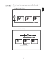
Page 10: ...8 Ein Beschalten des Relais ist wie folgt möglich Relais als Öffner und als Schließer Als Öffner Als Schließer ...

Page 11: ...r Wechselrich ter Sollten Sie mehrere Wechselrichter mit nur einer Signaleinrichtung z B Lampe überwachen wollen können Sie die Fronius Signal Card wie folgt an den externen Stromkreis anschließen Parallel als Schließer In Serie als Öffner ...

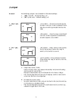
Page 12: ...rärer Service Code öfter als 50 Mal pro Tag auftreten B Dauerhafte Service Codes Service Codes die zumeist einen Defekt des Wechselrichters betref fen und zu einem Stillstand des Wechselrichters führen z B Hard ware Defekt Die Fronius Signal Card reagiert sollte ein dauerhafter Service Code länger als 4 15 Stunden angezeigt werden Stellung off Wird ein Service Code angezeigt schaltet nur das Relai...

Page 13: ...hter eine Taste gedrückt wird Oder ein Trennen und erneutes Zuschalten der DC Versorgung erfolgt Das Relais ist von der Versorgung der Fronius Signal Card und der Elek tronik galvanisch getrennt potentialfreier Kontakt Eine eigenständige Versorgung der angeschlossenen Verbraucher ist daher erforderlich Versorgung Wichtig Erst eine erneutes Zuschalten der DC Versorgung setzt das Relais in die Ausga...

Page 14: ... Relais U DC 50 V I DC 1 A U AC 250 V I AC 4 A Maximaler Leitungsquerschnitt 1 5 mm Leitung Empfohlenes Anschlusskabel 3 polige 0 75 mm Mantelleitung Der Summer ertönt nur solange wie der Wechselrichter von den Solarmodulen versorgt wird Das Relais bleibt in geschalteter Stellung auch wenn die DC Versor gung aufgrund von Dunkelheit nicht mehr gegeben ist Das Quittieren des Service Codes und damit ...

Page 15: ...g of the the Froni us Signal Card may only be carried out in accordance with the technical regulations It is essential that you read the Safety regulations chapter before commissioning the equipment or carrying out maintenance work WARNING Indicates a potentially dangerous situation Death or serious injury may result if appropriate precautions are not taken CAUTION CAUTION Indicates a situation wh...

Page 16: ...he design and operation of the inverter ensures maximum safety when installing the Fronius Signal Card The DC and AC sides are fully galvani cally electrically isolated from one another to ensure optimum levels of safety To provide maximum safety during operation the connections of the Fro nius Signal Card are also fully galvanically electrically isolated Never route leads connected to the Fronius...

Page 17: ...fety 5 Fronius Signal Card 5 Please note 5 Connection cable specification 5 Installing the Fronius Signal Card 6 Connecting the circuit 7 Features of a compatible circuit 7 3 pin terminal 7 Relay as an NC and NO contact 8 Simultaneous monitoring of several inverters 9 Jumper 10 General 10 1 Buz jumper 10 2 Err jumper 10 Power supply 11 DC supply 11 Relay as a floating contact 11 Operation 11 Gener...

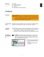
Page 18: ...card and can only ever monitor one inverter at a time The Fronius Signal Card detects serious inverter malfunctions If a malfunction is detected the Fronius Signal Card trips a relay and also emits an acoustic signal see Jumper chapter The relay activates a consumer chosen by the user e g a visual or acoustic alarm Fronius Signal Card 1 Connection cable 2 pin or 3 pin sheathed cable 2 Component fr...

Page 19: ...and DC voltage from solar modules The connection compartment should only ever be opened by an authorised electrical engineer The separate hou sing containing the power modules must only be opened by a Fronius trained service technician and only when in a de ener gised state NOTE The effectiveness of the strain relief device is only guaran teed for cables of a certain thickness Fronius recommends a...

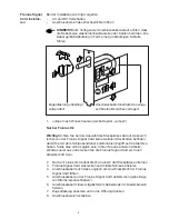
Page 20: ... cable through the hole in the Fronius Signal Card connection plate 5 Connect the connection cable to the Fronius Signal Card see Con necting the circuit 6 Secure the connection cable in the clamping area using the cable tie supplied 7 Fit the strain relief device and press into the opening 8 Close connection compartment Strain relief device must be used at all times Route the connection cable wit...

Page 21: ...tage 250 V DC Maximum AC current 4 A DC Maximum cable cross section Up to 1 5 mm cable NOTE The effectiveness of the strain relief device is only guaran teed for cables of a certain thickness Fronius recommends a 3 pin 0 75 mm sheathed cable or a cable of equivalent thickness Connecting the circuit Features of a compatible circuit The relay off position is marked directly on the PC board and appea...

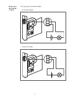
Page 22: ...8 The relay may be wired as follows Relay as an NC and NO contact As an NC contact As an NO contact ...

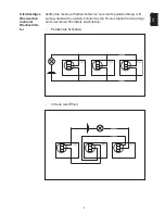
Page 23: ... of several inver ters If you wish to monitor several inverters with just a single signalling device e g light connect the Fronius Signal Card to the external circuit as follows Parallel as an NO contact In series as an NC contact ...

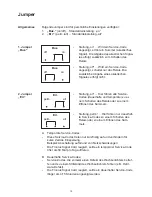
Page 24: ... Fronius Signal Card reacts if a temporary service code occurs more than 50 times in a single day B Permanent service codes Service codes that concern at least one fault in the inverter and cau se it to stop e g hardware fault The Fronius Signal Card reacts if a permanent service code is sig nalled for longer than 4 15 hours off position Only the relay is switched if a service code is signalled An...

Page 25: ...ntil a button is pressed on the inverter or the DC supply is switched off and back on again The relay is galvanically electrically isolated floating contact from the Fronius Signal Card supply and the electronics An independent power supply for the consumers is therefore necessary Power supply Important Only switching the DC supply back on will return the relay to its original position As a result...

Page 26: ... DC 50 V I DC 1 A U AC 250 V I AC 4 A Maximum cable cross section 1 5 mm cable Recommended connection cable 3 pin 0 75 mm sheathed cable The buzzer only sounds while the inverter is being supplied with power from the solar modules The relay remains in its switched position even when the DC supply is terminated due to the onset of darkness A service code can only be acknowledged and the relay reset...

Page 27: ...1 Z H ...

Page 28: ...2 ...

Page 29: ...3 Z H ...

Page 30: ...4 1 4 5 8 6 7 3 2 9 ...

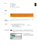
Page 31: ...5 Z H 15 mm 5 mm ...

Page 32: ...6 ...

Page 33: ...7 Z H ...

Page 34: ...8 ...

Page 35: ...9 Z H ...

Page 36: ...10 Buz off on Buz off on Err perm all Err perm all ...

Page 37: ...11 Z H ...

Page 38: ......

Page 39: ...www fronius com USA A Fronius Worldwide www fronius com addresses Fronius USA LLC Solar Electronics Division 10421 Citation Drive Suite 1100 Brighton MI 48116 E Mail pv us fronius com http www fronius usa com Under http www fronius com addresses you will find all addresses of our sales branches and partner firms ...

Reviews: