6
1.
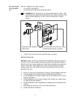
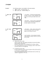
Set the jumper as desired (see „Jumper“ chapter)
Fronius IG Plus only:
Important!
To allow sufficient screwdriver access to the terminal, ensure
that there are no plug-in cards to the right of the slot earmarked for the
Fronius Signal Card. Should this not be possible, complete all other steps
first and only plug the Fronius Signal Card in after completing step 6.
2.
Fronius IG Plus only: Remove the cover plate from one of the slots
3.
Insert the Fronius Signal Card and secure with a screw
4.
Guide the connection cable through the hole in the Fronius Signal
Card connection plate
5.
Connect the connection cable to the Fronius Signal Card (see „Con-
necting the circuit“)
6.
Secure the connection cable in the clamping area using the cable tie
supplied
7.
Fit the strain-relief device and press into the opening
8.
Close connection compartment
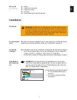
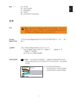
Strain-relief device must
be used at all times.
Route the connection cable within
the marked area.
Installing the
Fronius Signal
Card
To install, proceed as follows:
-
Disconnect AC and DC
-
Open the inverter connection area
NOTE!
When routing the connection cable, ensure that it does not
come into contact with any electronic parts or edges. Lay the cable
as a large loop as shown in the diagram.
Summary of Contents for Signal Card
Page 2: ......
Page 27: ...1 Z H ...
Page 28: ...2 ...
Page 29: ...3 Z H ...
Page 30: ...4 1 4 5 8 6 7 3 2 9 ...
Page 31: ...5 Z H 15 mm 5 mm ...
Page 32: ...6 ...
Page 33: ...7 Z H ...
Page 34: ...8 ...
Page 35: ...9 Z H ...
Page 36: ...10 Buz off on Buz off on Err perm all Err perm all ...
Page 37: ...11 Z H ...
Page 38: ......


