background image

Screen

Code

Description

Values

MEASurE

P6

Measurement mode **

A: easy connection, measures
all energy without taking the
direction into account.
B*: measures imported and
exported energy separately.

InStALL

P7

Connection check

On: activated
Off*: deactivated

P int

P8

Average power calculation
interval (minutes)

1* - 30

MOdE

P9

Display mode **

Full*: full display
Easy: reduced display. The
values that are not displayed
are still transmitted via the
serial interface.

tArIFF

P10

Tariff management **

On: activated
Off*: deactivated

HoME

P11

Screen showing measured
variables displayed at startup
and after 120 seconds of
inactivity **

For full display (Mode = Full):
0* - 19

AddrESS**
*

P14

Modbus address

1* - 247

bAUd

P15

Baud rate (kBit/s) **

9.6* / 19.2 / 38.4 / 57.6 / 115.2

PArITY

P16

Parity **

Even/No*

STOP bit

P16-2 Only if parity = No. Stop bit **

1* / 2

rESET

P17

Activation of the reset function
for energy tariffs, maximum
requested power and part val-
ues of active and reactive
energy (the latter are only
transmitted via the serial inter-
face) **

No*: reset function deactiv-
ated.
Yes: reset function activated.

End

P18

Returns to the measured vari-
ables start screen

None

*

Factory settings

**

The settings can be protected by changing the default password (password can-
not be reset).

***

Settings that need to be configured.

Setting the trans-
formation ratio of
the current and
voltage trans-
formers

Only the transformation ratio of the current and voltage transformers must be set. All
other parameters are preset at the factory.

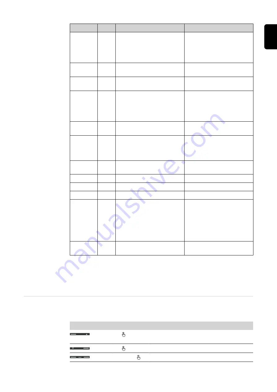
Symbol

Name

Event

Function

Up

1 x 

Scroll one screen forward, increase the value by
1

Down

1 x 

Scroll one screen back, decrease the value by 1

Enter

2 seconds 

Call up settings, confirm value

27

EN

Summary of Contents for Smart Meter TS 5kA-3

Page 1: ...rced from certified sustainable forests FSC Perfect Charging Perfect Welding Solar Energy Fronius Smart Meter TS 5kA 3 EN Operating instructions PV system monitoring 42 0426 0348 EN 005 28072020 www youtube com FroniusSolar LEARN MORE WITH OUR HOW TO VIDEOS ...

Page 2: ......

Page 3: ...nating resistors Explanation of symbols 23 Terminating resistors 23 Multi meter system Explanation of symbols 24 Multi meter system 25 Parameters menu 26 Setting the transformation ratio of the current and voltage transformers 27 Setting the address on the Fronius Smart Meter TS 28 Start up 31 Fronius SnapINverter 33 General 33 Connecting to the Fronius Datamanager 33 Configuring the Fronius Smart...

Page 4: ...4 ...

Page 5: ...Safety rules 5 ...

Page 6: ...6 ...

Page 7: ...here is a danger of Injury or death to the operator or a third party Damage to the device and other material assets belonging to the operating company Any safety devices that are not fully functional must be repaired by an authorised spe cialist before the device is switched on Never bypass or disable protection devices For the location of the safety and danger notices on the device refer to the s...

Page 8: ...N rail with corresponding back up fuses which are adapted to the cable cross sections of the copper conductors and to the maximum cur rent of the meter The Fronius Smart Meter TS must only be operated in accordance with the specifications in the enclosed documentation and in accordance with local laws reg ulations provisions standards and within the limits of technical possibilities Any use of the...

Page 9: ...mplementation as national law electrical equipment that has reached the end of its life must be collected separately and returned to an approved recycling facility Any device that you no longer require must be returned to your distributor or disposed of at an approved collection and recyc ling facility in your area Ignoring this European Directive may have potentially adverse effects on the enviro...

Page 10: ...10 ...

Page 11: ...General information 11 ...

Page 12: ...12 ...

Page 13: ...al electricity meter which optimises self con sumption and records the household s load curve In conjunction with the Fronius inverter Fronius Datamanager and Fronius data interface the Fronius Smart Meter TS provides a clear overview of a user s own power consumption The meter measures the power flow to the loads or to the grid and forwards the informa tion via the Modbus RTU RS485 communication ...

Page 14: ...nstalled in the following positions in the system Positioning at the feed in point 0 0 16 7 Positioning at consumption point 0 0 16 7 For use as a secondary meter to measure individual loads and producers see chapter Multi meter system on page 25 14 ...

Page 15: ...Installation 15 ...

Page 16: ...16 ...

Page 17: ...y set terminating resistors see Terminating resistors on page 23 11 Tug on each wire and plug to make sure that they are securely connected to the ter minal blocks 12 Switch on the power supply to the Fronius Smart Meter TS 13 Check the firmware version of the Fronius system monitoring To ensure compatibil ity between the inverter and the Fronius Smart Meter TS the software must always be kept up ...

Page 18: ...on which must interrupt both neutral and non earthed cables concurrently Auxiliary power supply cabling IMPORTANT An auxiliary power supply is required to operate the Fronius Smart Meter TS The fuse must match the dimensions of the conductors L N N L Cabling IMPORTANT Always switch off the power supply before connecting the mains voltage inputs to the Fronius Smart Meter TS Recommended thickness o...

Page 19: ...1N1E 3 2E 1 3 3 2E 1 3 3 3E 19 EN ...

Page 20: ...not use current transformers with a voltage output Current transformers are directional If they are mounted backwards or with swapped wires the measured power will be negative Primary current Maximum current per phase A current converter with a primary current greater than the 20 ...

Page 21: ...tion of the Fronius Smart Meter TS is 0 5 VA Line resistance 0 6 VA self consumption 0 5 VA 1 1 VA A current transformer with a rating of 1 5 VA 5 VA or higher is suitable here Accuracy class Use Class 1 or better Class 0 5 0 2 etc Class 1 is equivalent to a deviation of 1 of the secondary current at maximum power Mounting Rigid or hinged Rigid is usually cheaper with better power and accuracy val...

Page 22: ...rs can be installed in the system see chapter Multi meter system on page 25 Fronius Inverter ON D D OUTPUT RS 485 T D M M D GND To avoid interference the terminating resistor must be used see chapter Terminating resistors on page 23 This is integrated in the Fronius Smart Meter TS and must be manufactured with a wire between M and T T termination ATTENTION More information on successful commission...

Page 23: ...d T Modbus RTU slave e g Fronius Ohmpilot Fronius Solar Battery etc Terminating resistor R 120 Ohm Terminating res istors Due to interference it is recommended that terminating resistors are used as illustrated below to ensure proper functioning OPTION 1 0 0 16 7 Manufacturer manual max 300 m GND T D M M D 0 0 16 7 Manufacturer manual Manufacturer manual OPTION 2 max 300 m GND T D M M D 23 EN ...

Page 24: ...n the system if insufficient power is being generated by the solar modules or supplied by the battery Inverter in the system e g Fronius Primo Fronius Symo etc 0 0 16 7 Utility meter Measures the measurement data relevant for billing amounts of energy in particular kilowatt hours of energy sourced from the grid and energy fed into the grid Based on the relevant billing data the electricity retaile...

Page 25: ...mption branch and provides measurement data for energy pro filing in Fronius Solar web Loads in the system e g washing machine lamps TV etc Additional loads in the system e g heat pump Additional producers in the system e g wind power plant Terminating resistor R 120 Ohm Multi meter sys tem If several Fronius Smart Meter TS are installed a separate address must be set for each see Setting the addr...

Page 26: ...ned individually for each channel For PV systems with inverters from the Fronius GEN24 and Fronius Tauro product series the following must be observed The primary meter and the battery must be connected to different channels The remaining Modbus participants must be distributed equally Parameters menu Screen Code Description Values PASS P1 Enter the current password 2633 nPASS P2 Password change F...

Page 27: ...ArITY P16 Parity Even No STOP bit P16 2 Only if parity No Stop bit 1 2 rESET P17 Activation of the reset function for energy tariffs maximum requested power and part val ues of active and reactive energy the latter are only transmitted via the serial inter face No reset function deactiv ated Yes reset function activated End P18 Returns to the measured vari ables start screen None Factory settings ...

Page 28: ... for 2 seconds to exit the settings Ratio of current transformers1 0001 10002 Ratio of voltage transformers1 3 001 0 10002 1 Important Changing the transformation ratios will reset the counters in the Fronius Smart Meter TS to 0 2 Transformation ratio in the current transformer x Transformation ratio of the voltage transformers max 1000 3 Changeover only when using voltage transformers direct volt...

Page 29: ... Down and confirm each individual value with Enter P14 AddrESS 001 PrG 1 Use Up or Down to access the P14 screen 2 Press and hold Enter for 2 seconds 3 Set the address with Up and Down and confirm each individual value with Enter 4 Press Up to access screen P18 and press and hold Enter for 2 seconds to exit the settings 29 EN ...

Page 30: ...30 ...

Page 31: ...Start up 31 ...

Page 32: ...32 ...

Page 33: ...ager IP switch in the A position 3 In the browser address bar enter and confirm the IP address http 169 254 0 180 and confirm Configuring the Fronius Smart Meter TS as the primary meter 1 Go to the Fronius Datamanager website Open the web browser In the address bar of the browser enter the IP address IP address for WLAN 192 168 250 181 IP address for LAN 169 254 0 180 or the host and domain name o...

Page 34: ... 180 or the host and domain name of the Fronius Datamanager and confirm The Fronius Datamanager website will be displayed 2 Click the Settings button 3 Log in to the login area with the service user and the service password 4 Call up the Meter menu area 5 Select the secondary meter from the drop down list 6 Click the Add button 7 Enter the name of the secondary meter in the Name input field 8 Ente...

Page 35: ...e inverter in the network settings the inverter is dis played with the name FRONIUS_PILOT and the serial number of the device 3 Password enter 12345678 and confirm IMPORTANT To enter the password on a Windows 10 operating system the link Connect using a security key instead must first be activated to establish a connection with the pass word 12345678 4 In the browser address bar enter and confirm ...

Page 36: ...the meter feed in point or con sumption point For more information on the position of the Fronius Smart Meter TS see Positioning on page 14 7 Click the Add button 8 Click the Save button to save the settings The Fronius Smart Meter TS is configured as a primary meter Configuring the Fronius Smart Meter TS as a secondary meter 1 Access the inverter website Open the web browser In the address bar of...

Page 37: ...Operation Menu structure A graphic view of the menu structure can be found in the User Information that is sup plied as standard 37 EN ...

Page 38: ...quency Tolerance 50 60 Hz 45 65 Hz Nominal current lb 1 A 5 A Maximum current Imax 6 A Starting current 10 mA Current transformer ratio kCT 1 1000 e g TC 800 5A kCT 160 for direct connection kCT 1 Short time overload EN IEC 62053 21 EN IEC 62053 23 5 lmax 0 5 s Self consumption current path max cur rent 0 3 W per phase Maximum value kVT x kCT 1000 CT 5A Current distortion factor in acc with EN IEC...

Page 39: ...d auxiliary voltage Standard RS485 3 conductors Transmission Serial asynchronous Protocol Modbus RTU Addresses 1 255 Number of bits 8 Stop bit 1 Parity bit None even odd Baud rate 9600 19200 38400 bit s Response time 200 ms Insulation EN IEC 62052 11 EN IEC 62053 21 Installation category III Degree of pollution 2 Insulation voltage 4 kV RMS Impulse withstand voltage Test circuit 4 kV 1 2 60 µs Vol...

Page 40: ... 35 mm DIN rail Housing material Noryl self extinguishing Degree of protection EN 60529 IP54 housing IP20 connections Weight 240 grams Terminals Measuring input Wire Min 1 mm max 4 mm Recommended torque max 0 6 Nm Data output Wire min 0 05 mm Recommended torque max 0 4 Nm Fronius manufac turer s warranty Detailed country specific warranty terms are available on the internet www fronius com solar w...

Page 41: ...41 EN ...

Page 42: ...42 ...

Page 43: ...43 EN ...

Page 44: ...S INTERNATIONAL GMBH Froniusstraße 1 A 4643 Pettenbach AUSTRIA contact fronius com www fronius com Under www fronius com contact you will find the addresses of all Fronius Sales Service Partners and locations ...

Reviews: