


53
EN
If the Feeder inching button is released and pressed again before one second has elapsed,
the sequence starts again from the beginning. This makes it possible to continuously po-
sition the wire at a low wire feed speed of 1 m/min or 39.37 ipm where necessary.
If there is no Feeder inching/Gas test button, the
torch trigger
can be used in the same
way. Before using the torch trigger for wire threading, proceed as follows:
Press the Mode button to select 2-step mode
Set the "Ito" parameter to "Off" in the set-up menu
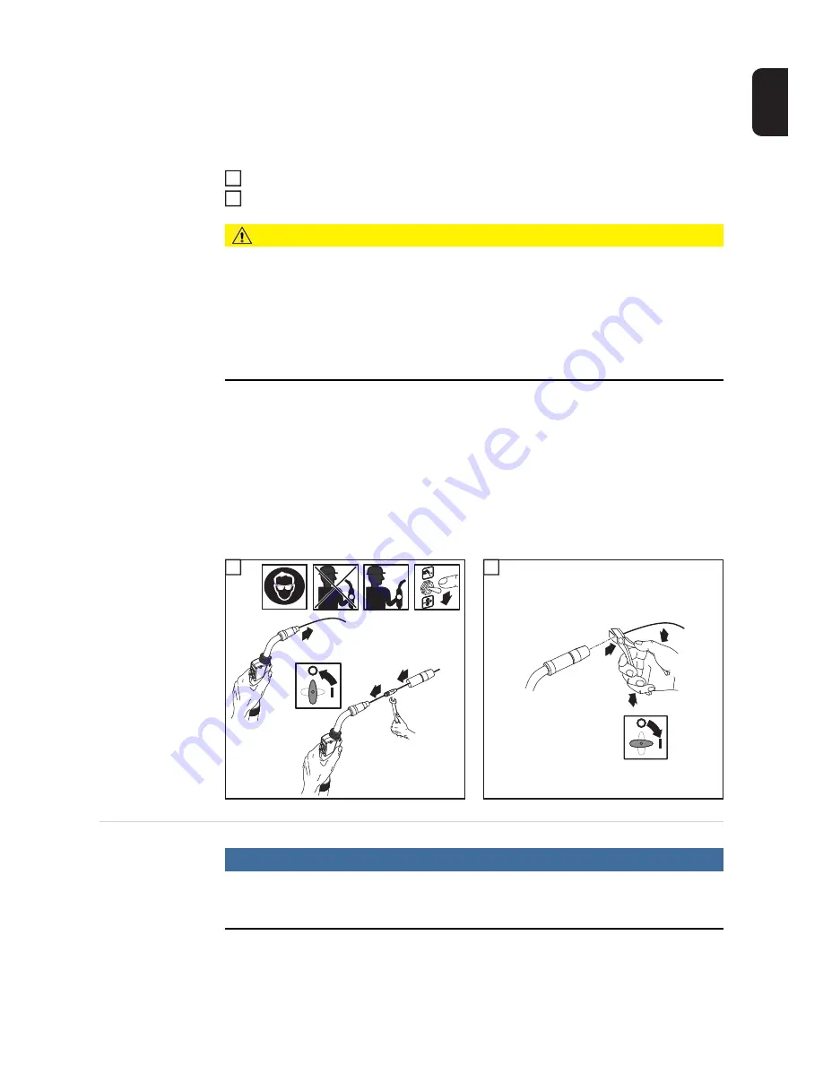
CAUTION!
Risk of injury and damage from electric shock and from the wire electrode emerging
at speed from the torch.
When pressing the torch trigger:
► keep the welding torch away from your face and body
► wear suitable protective goggles
► do not point the welding torch at people
► make sure that the wire electrode does not touch any conductive or earthed parts, such
as the housing, etc.
IMPORTANT!
If the
torch trigger
is pressed instead of the Feeder inching/Gas test but-
ton, the welding wire runs at the feeder creep speed (depending on the welding program)
for the first 3 seconds. After these 3 seconds, wirefeeding is briefly interrupted.
The welding system detects that the welding process should not start, but that the wire is
to be threaded. At the same time, the gas solenoid valve closes, and the welding voltage
on the wire electrode is switched off.
If the torch trigger is held down, wirefeeding restarts immediately without shielding gas and
welding voltage, and the process continues as described above.
1
2
Setting the con-
tact pressure
NOTE!
Set the contact pressure in such a way that the wire electrode is not deformed but
nevertheless ensures proper wirefeeding.
1
2
2
4
5
3
1
3
1
1
2
3
4
Summary of Contents for VR 5000 noSpool
Page 2: ...2...
Page 4: ...4...
Page 19: ...General information...
Page 20: ......
Page 25: ...Control elements and connections...
Page 26: ......
Page 41: ...Installation and commissioning...
Page 42: ......
Page 51: ...51 EN 1 2 1 2...
Page 58: ...58...
Page 59: ...Welding...
Page 60: ......
Page 76: ...76 Number 3 Number 4 Number 5...
Page 77: ...Setup settings...
Page 78: ......
Page 92: ...92...
Page 93: ...Troubleshooting and maintenance...
Page 94: ......
Page 105: ...Technical data and settings tables...
Page 106: ......
Page 123: ...Appendix...
Page 125: ...125...
Page 127: ...127 8 8 8 8 5 5 5 Motor Plate Alu 4R s Connector Motor...
Page 128: ...128...
Page 129: ...129...
Page 130: ...130...
Page 131: ...131...


