


62
MIG/MAG modes
General
WARNING!
Operating the equipment incorrectly can cause serious injury and damage.
Do not use the functions described until you have thoroughly read and understood the fol-
lowing documents:
► these operating instructions
► all the operating instructions for the system components, especially the safety rules
For details of the meaning, settings, setting range and units of the available welding pa-
rameters (e.g. gas pre-flow time), please refer to the "Set-up parameters" section.
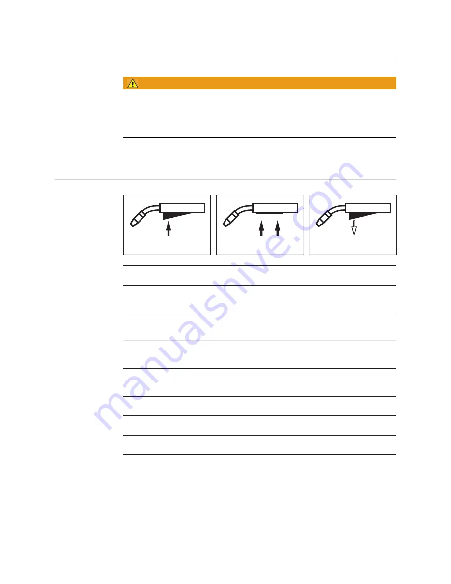
Symbols and
their explanations
Press the torch trigger
Hold the torch trigger
Release the torch trigger
GPr
Gas pre-flow time
I-S
Starting current
can be increased or decreased depending on the application
SL
Slope: the starting current is continuously lowered as far as the welding current and the
welding current as far as the final current
I
Welding-current phase: uniform thermal input into the base material, whose temperature
is raised by the advancing heat
I-E
Final current
for filling the end-crater.
GPo
Gas post-flow time
SPt
Spot welding time / stitch welding time
SPb
Stitch pause time
Summary of Contents for VR 5000 noSpool
Page 2: ...2...
Page 4: ...4...
Page 19: ...General information...
Page 20: ......
Page 25: ...Control elements and connections...
Page 26: ......
Page 41: ...Installation and commissioning...
Page 42: ......
Page 51: ...51 EN 1 2 1 2...
Page 58: ...58...
Page 59: ...Welding...
Page 60: ......
Page 76: ...76 Number 3 Number 4 Number 5...
Page 77: ...Setup settings...
Page 78: ......
Page 92: ...92...
Page 93: ...Troubleshooting and maintenance...
Page 94: ......
Page 105: ...Technical data and settings tables...
Page 106: ......
Page 123: ...Appendix...
Page 125: ...125...
Page 127: ...127 8 8 8 8 5 5 5 Motor Plate Alu 4R s Connector Motor...
Page 128: ...128...
Page 129: ...129...
Page 130: ...130...
Page 131: ...131...


