23
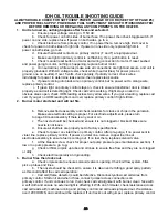
IDH OIL TROUBLE SHOOTING GUIDE
ALWAYS DOUBLE CHECK FOR SUFFICIENT POWER , GAUGE OF CORD (SEE TOP OF PAGE #5)
AND PROPER FUEL SUPPLY. POWER AND FUEL SUPPLY MUST BE SHUT OFF/DISCONNECTED
BEFORE REMOVING OR REPLACING ANY COMPONENTS ON THE HEATER.
1
.
Unit is turned on, nothing happens after 5 second safe start.
a. Ensure proper voltage coming in, 115V AC.
b. Check for power on both sides of burner fuse. If no power, then check toggle switch. If
power on one side, replace fuse. If power on both sides, go to
c.
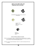
c. Check black wire from primary control. If no power there, remove high limit cover &
check for power on both sides of high limit. If power on one side only, replace high limit. If
power on both sides, go to
d.
d. Ensure thermostat contacts on primary control ( T and T) are jumpered out.
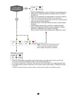
e. Make sure light on primary control is not flashing. If so, push button to reset.
f. Check manual reset button on motor and wiring connection to motor. If reset pushed
and power going to motor, nothing is happening, replace burner motor.
g. On neutral line ( white wires) make sure all connections are tight and secure, and unit is
properly grounded. With AC voltage tester, check white (neutral lines) for power (one on
ground, one on neutral). If over 5 volts, check polarity. If polarity correct, check wires
individually for power to determine leak source, then replace leak source.
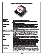
h. If power coming into black wire on primary control, but no power out to orange wire,
replace primary control.
i. If green light on primary control stays on, check to ensure transformer door is closed
properly as cad cell is detecting light. Check cad cell is working. If light stays on and no
obvious areas open, check OHM reading across two yellow wires. If you get a reading, replace cad
cell. If you get no OHM reading from cad cell, replace primary control if light still on.
2.
Burner motor starts but unit will not fire.
b. Remove electrode assembly and check isolators for cracks or chips in the porcelain.
Make sure electrode setting is proper. For electrode adjustments, please turn
to page 9.Clean assembly if there is any soot or oil..
c The nozzle should be checked and ensure it is not clogged or blocked. Make sure
nozzle is not loose.
d. Ensure air shutters are properly set to factory specifications.
e. Check for power on violet line on primary control. After pre-purge, if no power sent to
violet line, replace primary control. If power on violet line, remove copper fuel line at
electrode assembly to ensure fuel is coming out. If no fuel there, replace solenoid valve.
f. At the bleeder screw, check for proper out pump pressure (see maintenance section). If
low or no pump pressure, go to
g
g Check oil filter, oil pick up tube and oil lines to ensure free flow and they are not clogged
or dirty.
h Check electrical polarity and grounding.
3
.
Burner fires then locks out.
a. Check oil pressure to ensure solenoid valve is opening. Check oil flow system, filter,
pick up tubes and lines.
b. The nozzle should be checked to ensure it is clean and emitting a good spray pattern,
as this could affect the cad cell operation.
c. Cad cell (flame detector) could be defective. Disconnect yellow cad cell wires from
primary control. Start unit and when it fires, connect jumper across connections on
primary control. If unit continues to run, then check cad cell alignment with burner, clean face with
a soft cloth and ensure no external light is affecting it. With an ohmmeter, check resistance across
cad cell leads with machine running and primary control cad cell leads jumpered out. If resistance
over 1200 OHMS, cad cell should be replaced. If unit locks out with jumper, replace primary control.
Summary of Contents for IDH200QR LP
Page 15: ...15 IDH200LPNG QR OPERATING INSTRUCTIONS...
Page 16: ...16 IDH200LPNG QR OPERATING INSTRUCTIONS...
Page 17: ...17 IDH200 QR LPNG TROUBLE SHOOTING GUIDE...
Page 18: ...18 IDH200 QR LPNG TROUBLE SHOOTING GUIDE...
Page 19: ...19...
Page 20: ...20...
Page 21: ...21...

