

Introduction
The RB-30/RB-40 utilizes all the trusted attributes of the previous Redundancy Bus series along with adding new features
to meet the needs of an ever-growing range of users.
The upgraded redundancy hub
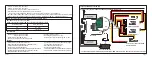
Previous redundancy bus models offered a dual-power with a dual-receiver design, the RB-30/RB-40 allows the user to use
a triple redundancy by adding a multiplex port (RX3 IN / SBUS Out) and uses a set of standard XT30/XT60 plugs which
provides a safe and efficient way to provide power.
Up to 24 PWM channels with overload protection
The RB-30/RB-40 supports connecting up to 24 high-voltage servos with overload protection added to each output channel.
Eight of the channels (CH1-8) are equipped with current sensors.
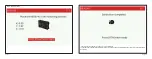
The diversified sensors
The RB-30/RB-40 is an extensive sensor module with a built-in gyroscope that supports model stabilizing functions and
includes other diversified telemetry feedback like the voltage, power consumption, altitude, and a lot more. It can be used
as an alternative to using a GR or S series receiver.
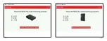
NFC Switch & Automatic data logging functions
The non-contact NFC switch is an external device that enables the power to be switched on/off on command without the
need to plug/unplug the battery connections. Once power is connected, the black-box function is automatically activated
and immediately starts recording the data.
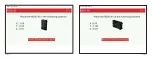
Menu scroll button, LCD screen & CNC case (RB-40 Only)
The RB-40 features a display screen that is comparable in size to one found on the X-Lite series radio. Navigating and
configuring telemetry data is even more convenient thanks to the scroll button. Even considering all these features while
maintaining durability, the RB-40 weighs only 260 grams thanks to the hybrid design of carbon fiber and aluminum
materials.
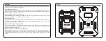
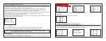
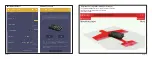
Overview
NON-CONTACT
SWITCH
VBAT1
VBAT2
DUAL POWER TRIPLE RECEIVER
TRIPLE GUARANTEE
24 CHANNEL SERVO INTERFACE
VOUT1
VOUT2
RX1
IN
RX2
IN
RX3
IN
/SB
US
OU
T
S.P
OR
T
RX1 S.
P
RX2 S.
P
Page 1
Page 2