
•
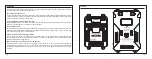
RX1 S.P-connect to the S.Port of RX1
•
RX2 S.P-connect to the S.Port of RX2
•
S.Port-connect to the S.Port of FrSky products with S.Port
•
RX1 IN~RX3 IN-connect to the SBUS OUT Port of the receiver.
* The RX3 IN can be switched to S.BUS OUT by the script or the Scroll button or the Freelink App.
•
BATTERY INPUT1&BATTERY INPUT2-connectors for batteries, supply power for RB-30/RB-40 and connected receivers.
•
OUTPUT1&OUTPUT2: SBEC OUTPUT, Continuous Current: 2*15A@5~8.4V (RB-30 ) / 2*30A@5~8.4V(RB-40)
External Blue LED
ON
OFF
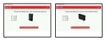
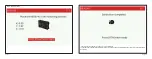
State (Self-check)
In process
Completing
CH1~CH24
-connect up to 24 servos (PWM)
*CH24 is used for the external LED when enable the stabilization function.
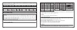
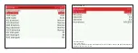
Specifications
•
Dimension: RB-30
:
114.4*73.4*18.7mm
RB-40: 163.2*100*23.5mm
•
Weight
:
RB-30: 100g / RB-40: 260g
•
Power connector: RB-30
:
XT30 / RB-40: XT60
•
Number of servos: up to 24
•
Operating temperature: -20
℃
~75
℃
•
Recommended input voltage range: DC 11~26V
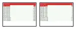
Features
•
Dual Power & Triple Receiver Guarantee
• High-voltage Servo Supported (Up to 24 PWM servos)
• Overload Protection on Each Channel
• Channel 1-8 with Current Detection
• Supports Stabilization Function with Built-in Gyroscope Sensor
• Multiple configuration methods (Lua script and FreeLink)
• Compatible with FrSky S.Port products
•
Various S.Port Telemetry Feedbacks (Voltage,
Current, Power Consumption, etc.)
• Black Box Data Record Function
• Non-contact Switch (Optional)
•
LCD Screen with Menu Scroll Button (
Only
RB-40)
•
CNC Aluminum & Carbon Fiber Case (
Only
RB-40)
Page 3
Page 4
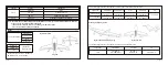
Note: Use voltage above 16.8V if you want to reach 30A@8.4V please.
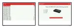
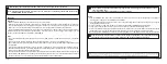
Layout: (take RB-30 for example)
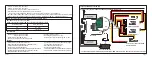
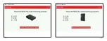
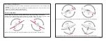
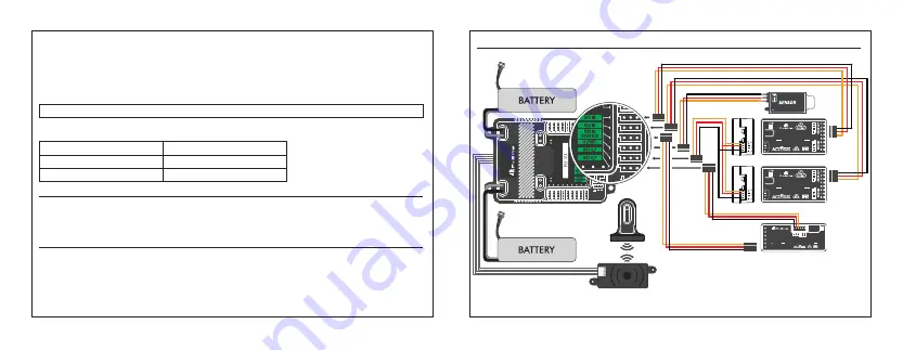
Dual-Frequency System (2.4GHz ACCESS & R9 SERIES) with RB Device
*
To use multi ACCESS receivers binding with the same ISRM module, please modify the
UID
for different receivers.
DUAL POWER TRIPLE RECEIVER
TRIPLE GUARANTEE
24 CHANNEL SERVO INTER
FACE
RB-30 / RB-40
2
2
8 / 2 4 C H T e l e m e t r y
R 8 P R O
2
2
8 / 2 4 C H T e l e m e t r y
R 8 P R O
R9 Series Receiver
ACCESS Series Receiver
DUAL POWER TRIPLE RECEIVER
TRIPLE GUARANTEE
24 CHANNEL SERVO INTER
FACE
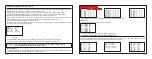
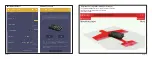
Non-contact Switch
CH1
CH2
CH3
CH4
CH5/
CH6/SBUS OUT
SBU
S
OUT
SBU
S IN
AIN
2
6/16 CH Long Range & Telemetry
R 9 S x
*
User also can replace the R9 SX
with the R8 PRO.


