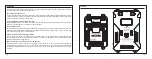


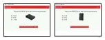

Introduction about two battery power supply
The RB-30/RB-40 supports DC 11V~26V. When two batteries are inserted at the same time, the higher SBEC output will be
selected to power the device. The maximum continuous current is 30A.
If the voltages of two power SBEC supplies are same, power can be used from both supplies at the same time;
If the voltages of two power SBEC supplies are different, the power comes from the one with the higher voltage.
Application of batteries with different capacity, number of cells and chemistry type is allowed.
Please ensure output power on one of the two power supplies is no less than the maximum operation power of the
connected devices (servos, etc.), or insufficient power supply on the connected devices may occur.
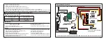
The RB-30/RB-40 supports two SBEC outputs, DC 5-8.4V.
The output voltage can be adjusted by the script or the Scroll button or the Freelink App. The supply voltage of CH1~CH24
and RX1~RX3 comes from the highest voltage.
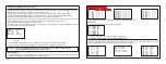
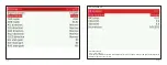
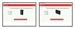
StabFunc. Enable
RX3 SBUS IN
Vout 1 Set 6.6V
Vout 2 Set 5.0V
Rx Protocol ACCESS
(RB-40)
* The Stabilization function can be enabled or disable by the script or the scroll button or Freelink APP.
* The RX3 SBUS IN can be switched to SBUS OUT by the script or the scroll button or Freelink APP.
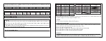
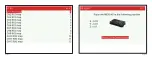
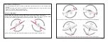
Channel Mapping:
1. The RB-30/RB-40 PWM 1 outputs the RX1 CH1 in default, if RX1 CH1 is not normal, it will switch to output the RX2 CH1
.
2. You can set the PWM output of RB-30/RB-40 from which RX channel.
Page 5
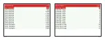
Ch17 Map 0 0 0
Ch18 Map 0 0 0
Ch19 Map 0 0 0
Ch20 Map 0 0 0
Ch21 Map 0 0 0
Ch22 Map 0 0 0
Ch23 Map 0 0 0
Ch24 Map 0 0 0
Ch 9 Map 9 9 9
Ch10 Map 10 10 10
Ch11 Map 11 11 11
Ch12 Map 12 12 13
Ch13 Map 13 13 13
Ch14 Map 14 14 14
Ch15 Map 15 15 15
Ch16 Map 16 16 16
* The Stabilization function should be disabled when you set the channel mapping.
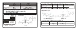
Failsafe set:
The channel outputs the value you set when into Failsafe.
Ch 1 FailSafe 800
Ch 2 FailSafe 800
Ch 3 FailSafe 800
Ch 4 FailSafe 800
Ch 5 FailSafe 800
Ch 6 FailSafe 800
Ch 7 FailSafe 800
Ch 8 FailSafe 800
* You can set up it by the script or the Scroll button or Freelink APP.
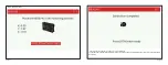
Overcurrent protection and current detection & state monitor
CH1~CH8 is equipped with current detection sensor, which can detect current in real time. CH1~CH24 have overload
protection. RB-30/RB-40 also monitors the status of each interface in real time.
Ch 1 Curr 0.3A
Ch 2 Curr 0.0A
Ch 3 Curr 0.1A
Ch 4 Curr 0.0A
Ch 5 Curr 0.0A
Ch 6 Curr 0.0A
Ch 7 Curr 0.0A
Ch 8 Curr 0.0A
(RB-40)
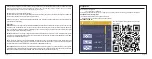
Rx1 No Connect
Rx2 No Connect
Rx3 No Connect
Sport1 Not Connect
Sport2 Not Connect
(RB-40)
Vbat1 Volt: 16.0V
Vbat1 Curr: 0.3A
Vbat1 Powe: 46mAh
Vout1 Volt: 6.6V
Vbat2 Volt: 0.0V
Vbat2 Curr: 0.0A
Vbat2 Powe: 0mAh
Vout2 Volt: 0.1V
(RB-40)
Page 6
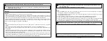
Caution: 1. Do not connect power supplies to CH1~CH24, S.PORT, RX1 S.P, RX2 S.P, RX1 IN ~RX3 IN.
2. Select the ACCESS/ACCST Rx Protocol before using it.
Ch 1 Map 1 1 1
Ch 2 Map 2 2 2
Ch 3 Map 3 3 3
Ch 4 Map 4 4 4
Ch 5 Map 5 5 5
Ch 6 Map 6 6 6
Ch 7 Map 7 7 7
Ch 8 Map 8 8 8
RB PWM1 RX1 CH1 RX2 CH1
RX3 CH1