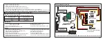

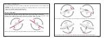
If current overload, the affected servo output will be disconnected from the power supply while remaining servo outputs are
still powered.
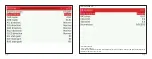
The allowed continuous current output on CH1~CH24, S.PORT, RX 1IN, RX 2IN,RX3 IN is 5A. When the continuous current
is over 10A, the RB-30/RB-40 will activate overload protection immediately 23
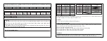
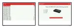
℃
.
Temperature
23
℃
50
℃
70
℃
I
hold
(A)
I
trip
(A)
10.00
5.00
3.95
3.35
7.90
6.70
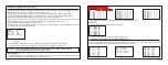
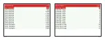
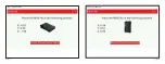
Display
OK
CHn / RXn_IN / SBUS_OUT / RX3_IN
Definition for Value
normal
CHn / RXn_IN / SBUS_OUT / RX3_IN overload
1.
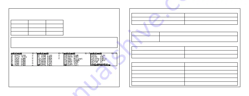
All values above will be transmitted to FrSky radio system in real time
AccX/Y/Z—Accelerometer triaxial parameter
CH1A~CH8A—The current telemetry of CH1 ~CH8
RBnC:
total power usage of battery n
RBnV:
the voltage of battery n
RBnA:
the current of battery n
RBCS:
About the telemetry values:
Note
I
hold
means the maximum current passes through the device without tripping under the above three conditions.
I
trip
means the minumum current passing through the device will cause trip under the above three conditions.
Page 7
Page 8
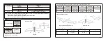
2. When using SD logs function, if the RBCS has a non-zero value, such as 64, Convert 64 to binary 1000000
,
As you can
see from the table, the channel 7 overloader or Voltage less than 4V.
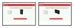
BitX
Bit n
(n≤15)
Definition for Value
0: channel n+1 normal
1: channel n+1 overloader or Voltage less than 4V
RBES: indication of CHN status.
Display
OK
CHn
Definition for Value
normal
CHn (n:17~24) overload
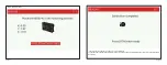
RBS
:
indication of receiver status.
Display
RX OK
RXn_FS
RXn_LOSTFRAME
RXn_PHYSICAL_CONNECTION _LOST
RXn_NO_SIGNAL
Definition for Value
normal
Receiver n Failsafe
Receiver n Lost frame
Receiver n Physical connection lost
Receiver n No signal