
Page 13
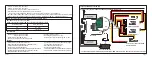
When Delta wing/Flying wing/V-tail is selected, the signal produced by the transmitter should be without active mixes on the
channels related to AIL and ELE. RB-30/RB-40 will mix the AIL(CH1) and ELE(CH2) input signal with a fixed mix percentage
automatically. Signals on CH4~CH8 then behave as required by user.
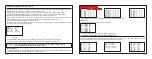
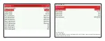
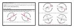
M:
represents a neutral signal period (1500μs)
H:
represents the time of required signal change to activate the mode (50μs). When the factory settings are selected, the
switch position shown above represents the required modes.
Off:
When the mode is activated, RB-30/RB-40 will transmit the received commands produced by the transmitter to the
model without compensating.
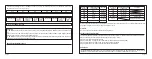
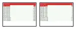
Flight mode:
Stabilization:
When the model is activated, RB-30/RB-40 will compensate with external forces (wind) as soon as receiving
commands from the transmitter. This function is used to enhance the stability of the model on three axis (Pitch, Roll, Roll).
CH9 could be used to adjust gyro gain by assigning a knob or a slider, changing the sensitivity of the counteracting signal
produced by the internal three-asis gyroscope.
Automatic level:
When the mode is activated, RB-30/RB-40 will make the model return to level orientation with internal
three-axis accelerometer and three-axis gyroscope on AIL and ELE channels after the sticks being released to neutral. RUD
channel works in stabilization mode only.
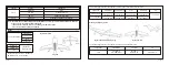
Hover:
When the mode is activated, RB-30/RB-40 will make the nose of the model straight up with internal three-axis
accelerometer and three-axis gyroscope on RUD and ELE channels. Under this mode, AIL is used to control the rotation of
the model and THR adjust the altitude. AIL channel works in stabilization mode only.
Knife-egde mode:
When the mode is activated, RB-30/RB-40 will roll the plane on a certain side (wing points up) with
internal three-axis accelerometer and three-axis gyroscope on RUD and AIL channels. While the mode steering is done with
ELE, altitude will be maintained with THR/RUD. ELE channel operates in stabilization mode only.
Page 14
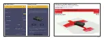
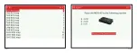
Configuration
Methods: APP configuration
FrSky radio LUA configuration
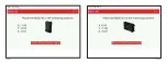
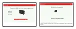
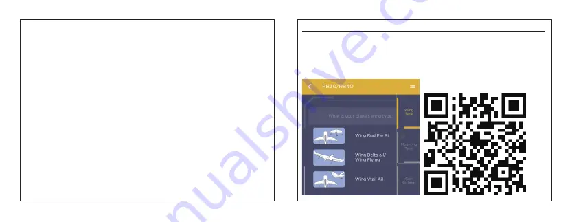
Parameters configuration: Wing type, mounting type, gain setting, offset angle setting, accelerometer calibration.
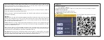
You can download the app and learn more about
how to use it.
APP(IOS/Android) configuration
:
•
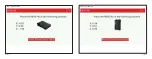
Connect the RB-30/RB-40 to the App with AirLink S.
The menu screen on the home page is displayed below:
RB30/RB40 STAB Set