6 horstCONTROL I/O
32
6.4
horstCONTROL I/O
This section describes how to connect devices to the horstCONTROL.
The connections can be split into four categories:
−
Safety-critical inputs/outputs
−
General digital outputs
−
+24 V power supply
−
Add-on interface
The inputs and outputs for this are located on the horstIO
–
the main control installed in the horstCON-
TROL
–
which is accessible on the horstCONTROL after removal of the cable duct. You can find a table
overview of the connectors and their terminal assignments in the Annex 13.6/13.7 from page 75.
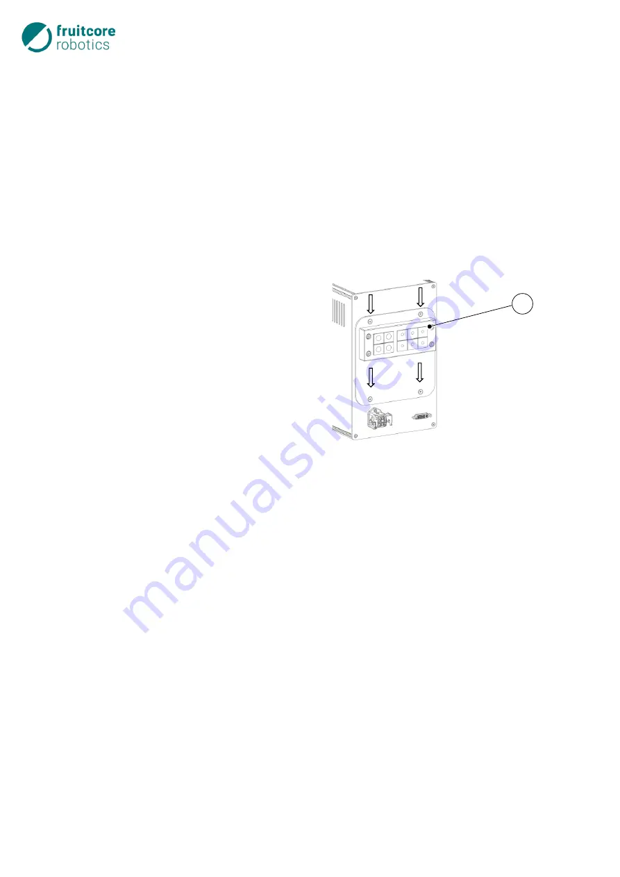
Undo the four external M4 countersunk head
screws.
Remove the cable duct cover (1).
The horstIO connections are now accessible.
If relevant, connect peripherals to the inter-
faces.
Secure the cable duct cover (1) again.
Fig. 6-4: horstCONTROL cable duct
The connections are designed as pluggable screw terminal connectors. The supplied screw terminal con-
nectors of type Amphenol Anytek TJ0831530000G (alternatively Phoenix Contact MC 1.5/ 8-ST-3.81) or
even Push-In terminals, such as Phoenix Contact FK-MCP1.5/8ST-3.8 can be used as connectors.
The connector base strip is of type Amphenol Anytek OQ0832500000G.
1
Summary of Contents for HORST900
Page 3: ...III ...


