6 horstCONTROL I/O
33
6.4.1
Overview of All Interfaces
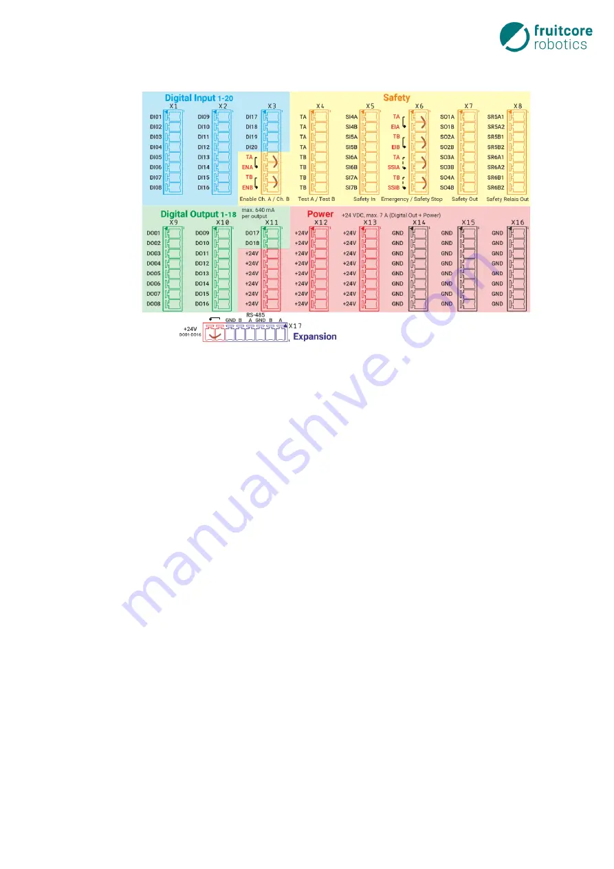
The following graphic shows the layout of the interfaces available on the horstIO.
Fig. 6-5: horstIO interfaces
−
7 safety-critical inputs
–
2-channels each (orange area)
o
3 dedicated inputs (orange area with red font)
▪
Emergency stop input
–
connection of potential-free contacts only
▪
Safety stop input
▪
Internal enabling switch
o
4 configurable outputs (external emergency stop, acknowledgement signals, etc.)
−
6 safety-critical outputs, 2-channels each (orange area, black font)
o
4 configurable outputs, push-pull
o
2 configurable, potential-free outputs (two relay contacts each)
−
Test signal generation TA/TB: OSSD signal for safety-critical inputs
−
Up to 28 general digital inputs (blue area)
o
20 digital inputs
o
A further 8 digital inputs, if the 4 configurable, safety-critical inputs are configured as normal
inputs
−
Up to 30 general outputs (green area)
o
18 digital outputs, Push-Pull / High-Side
o
A further 8 digital outputs, push-pull, if the 4 configurable, safety-critical outputs are config-
ured as normal outputs
o
A further 4 relay contacts, from the configurable, potential-free, safety-critical outputs, config-
ured as normal outputs
−
Shared GND and +24 V terminals (red area)
−
RS-485 interface for future extensions (purple area)
−
External bridge for +24 V: can be routed via the safety relay for safety-critical switch off of digital outputs
1-16.
−
An external enabling switch can be connected via terminals ENA/ENB and TA/TB, but deactivates the in-
ternal enabling switch on the horstPANEL.
Summary of Contents for HORST900
Page 3: ...III ...


