6 horstCONTROL I/O
35
Output Signal Switching Device (OSSD)
For safety-critical inputs, an output signal switching device (OSSD) can be activated. With an output signal
switching device activated, the output is periodically switched off and the input read back. If the results
do not match, an error is triggered. This means short circuits and cross-circuits can be monitored.
When using the OSSD function, the internal OSSD signals must be used. When external OSSD signals are
connected, the function must be deactivated in horstFX and the input filter activated. The configurable
time of the filter must be selected such that the test impulse is ignored (filter time > test impulse).
6.4.2.1
Emergency Stop and Safety Stop I/O
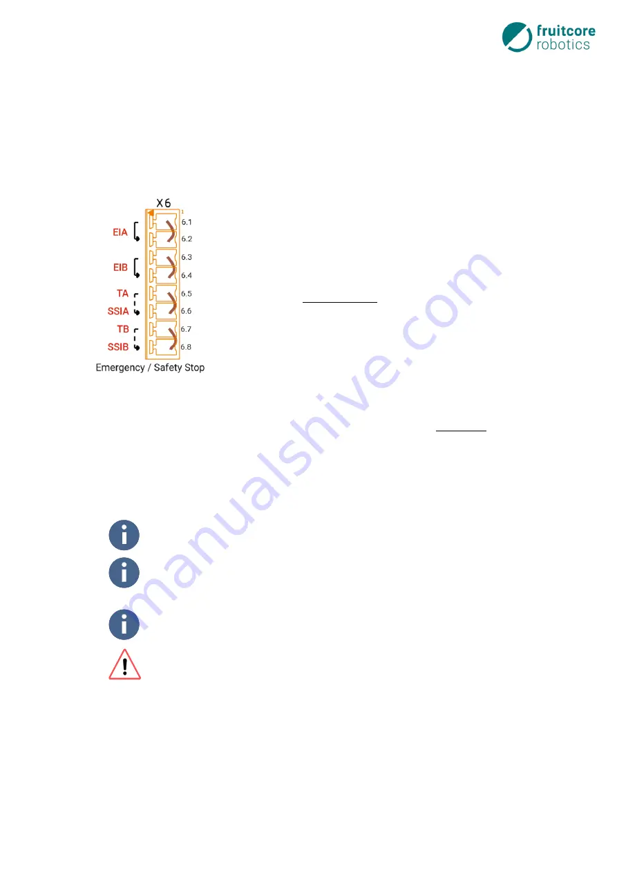
The inputs for emergency stop (EIA, EIB) and safety stop (SSIA, SSIB) are
available, dedicated inputs on every horstCONTROL (Safety In 1 & 2) and
therefore cannot be configured. They are redundant with performance level
“d”, category 3, as per EN ISO 13849
-1 and also meet the electrical specifi-
cations of the general digital inputs, see
signals are at terminal block X6.
The signal for emergency stop an (Emergency In) is at terminal X6.1 and
X6.3. These are fed in from test signal TA / TB for the output signal switch-
ing device and are routed to this terminal via the emergency stop on the
horstPANEL.
In the delivery state, bridges connect these to the safe emergency stop in-
puts X6.2 and X6.4. An external emergency stop button can be series-con-
nected to the emergency stop on the horstPANEL between X6.1 / X6.2 and
X6.3 / X6.4.
X6.6 and X6.8 are the respective inputs for a safety stop (Safety Stop In). At
these connections, either potential-free contacts and the internal cross-circuit detection via signals TA /
TB can be used, or an external safe output (e.g. safety laser scanner) can be connected.
For the emergency stop and safety stop input, it is possible to configure an input filter in horstFX in the
Safety I/O
menu. The maximum configurable time is 50 ms. See
Software Configuration Options for
The system is always in a safe state with "low" signals (0 V, logical 0), e.g. robot has a low
signal at the external emergency stop input.
If the robot has to be operated independently, bridges must be inserted in the terminals
for emergency stop, safety stop and enabling switch, see Fig. 6-6. These are inserted as
standard in the delivery state.
When integrated in a complete system, the robot system must be integrated in the
emergency stop circuit of the higher-level system.
When using an output signal switching device (OSSD), the signal is tested cyclically.
These test pulses must not cause a shut-down of all downstream control elements.
Please keep this in mind when selecting the devices to be connected.
Fig. 6-6: Emergency
stop/safety stop
connection
Summary of Contents for HORST900
Page 3: ...III ...


