6 horstCONTROL I/O
46
6.4.8.5
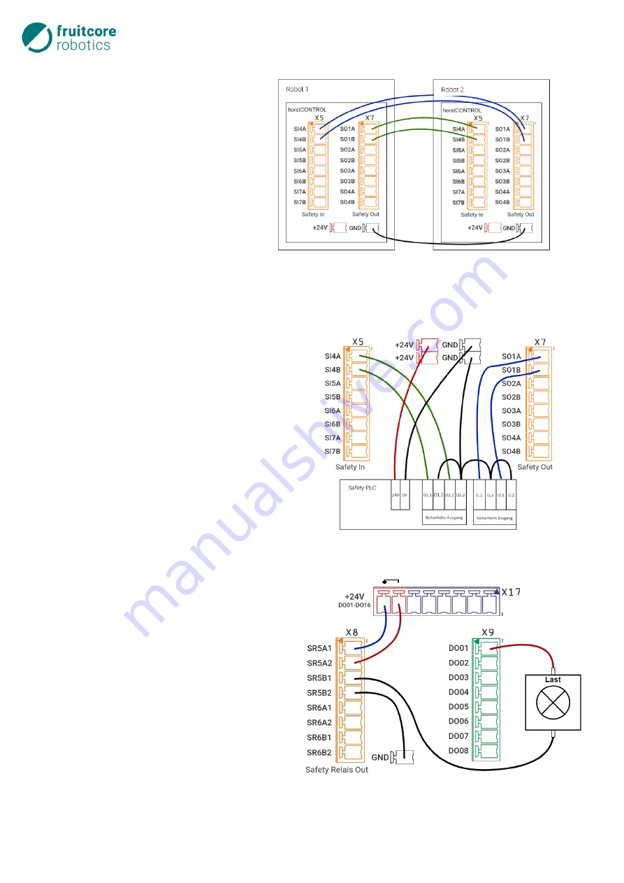
Connecting Emergency Stop for Several Devices
In a system, the robot should be integrated
in the emergency stop circuit of the other
devices so that there is no need, in an
emergency, to decide which emergency
stop button must be pressed. The adjacent
figure shows an example of the connec-
tion between two HORST robot systems.
In each case, a configurable safe output is
connected to a configurable safe input.
6.4.8.6
Connection to a Superordinate Safety
PLC
The robot should be integrated in a system in which
a safety PLC controls and monitors the safety func-
tions. A configurable safe output is connected to a 2-
channel input of the safety PLC here, and a configu-
rable safe input is connected to a 2-channel output
of the PLC.
6.4.8.7
Safe Deactivation of the Digital Outputs
General digital outputs DO01-16 should be deac-
tivated in a safety-critical manner. To this end,
the bridge between X17.7 and X17.8 is removed
and routed via the potential-free, safe output SR5
together with the ground connection. A con-
sumer connected to DO01 as shown in this ex-
ample is therefore safely deactivated. Note that
in this case all other consumers connected to the
general digital outputs DO01-16 are also deac-
tivated.
Fig. 6-23: Connecting emergency stop for several devices with each
other
Fig. 6-24: Superordinate safety PLC
Fig. 6-25: Safe deactivation of the +24 V supply
and the digital outputs
Summary of Contents for HORST900
Page 3: ...III ...


