6 Tool I/O
48
6.5
Tool I/O
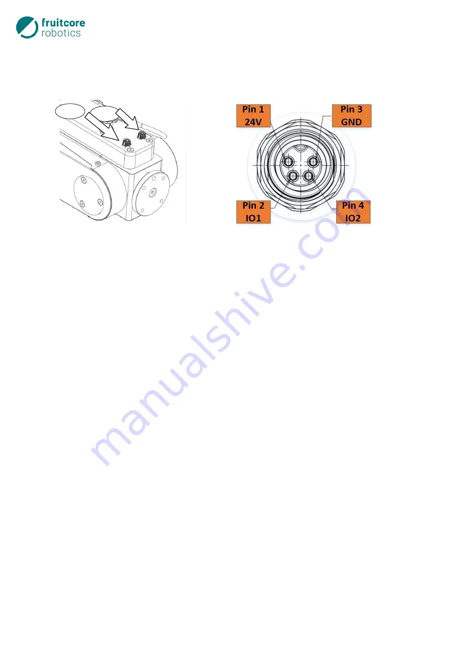
On support arm 3 of the robot, there are two interfaces (User 1, User 2), which supply current and control
signals for grippers and sensors that can be mounted at the tool interface of the support arm 3. Each of
these interfaces has two digital inputs/outputs as well as a +24 V power supply.
Fig. 6-29: Electrical connections for tools
Fig. 6-30: Tool I/O slot assignment
The interfaces are designed as 4-pin, A-coded M8 sockets (TE Connectivity T4071017041-001). As a
counter-piece, a plug connector with the following properties must be used:
M8 male, 4-ping, angled, A-coded.
The tool I/Os can be configured in horstFX as inputs or outputs (
Configuration of inputs/outputs
→
Spe-
cial I/O
menu). As standard, the two I/Os of the User 1 interface are configured as outputs and the two
I/Os of the User 2 interface are configured as inputs.
Configured as outputs, these act as Push-Pull switches and can be loaded with a maximum of 600 mA
each, if connected to the positive power supply, and a maximum of
200 mA each, if switched to ground. The maximum current-carrying capacity of all tool I/Os on
support arm 3, i.e. the four possible digital outputs and the +24 V power supply together, is
2.5 A.
Configured as inputs, these are compliant with IEC61131-2 Type 3.
A Functional diagram of this interface is provided in the Annex.
The parameters of the tool I/O are specified in the table on the next page.
User 1
User 2
Summary of Contents for HORST900
Page 3: ...III ...


