6 horstCONTROL I/O
40
6.4.5
General Digital Outputs
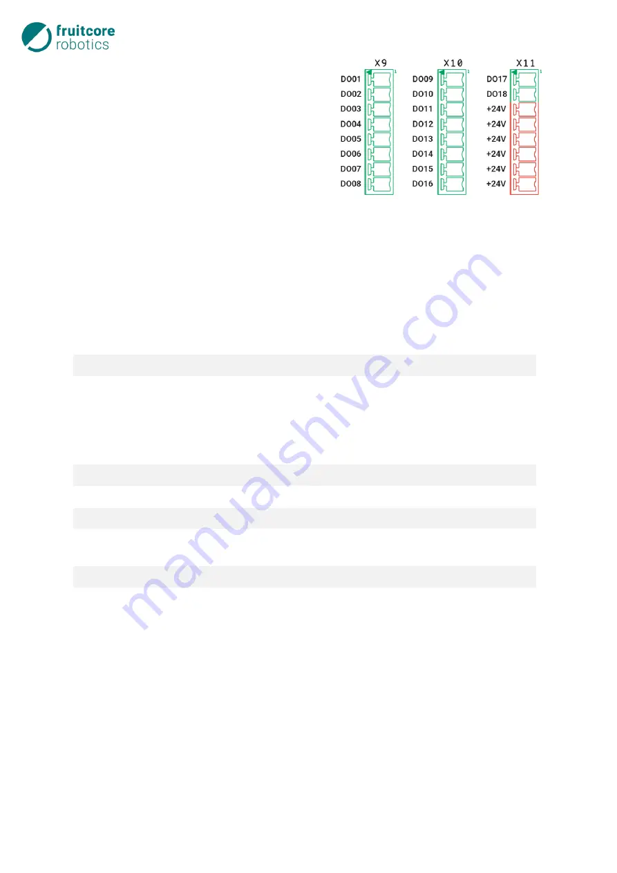
There are 18 general digital outputs available at ter-
minal blocks X9, X10 and X11. Outputs DO01 to
DO18 (Digital Out) are +24 V output channels and
can be configured as Push-Pull (switch to positive
supply voltage and to ground) or High-Side switches
(switch only to the positive supply voltage) via
horstFX.
If the
, page 38 are configured as gen-
eral outputs, up to 12 further outputs are available,
of which 4 are potential-free.
Each output can drive at least 640 mA if the signal is high (+24 V), and 440 mA if the signal is low (0 V).
The total current limit in section
page 42 applies. Ohmic, capacitive and inductive
loads can be switched. They are short-circuit proof and protected against ESD as well as voltage peaks
when switching inductive loads.
The following functions can be configured for the general digital outputs (see
Function
Description
Not assigned
-
Emergency stop button
Exact image of the emergency stop button signal, for diagnostics
(OR function with several emergency stop buttons). For larger sys-
tems, the actuated emergency stop button is easier to identify.
ATTENTION: There may be several emergency stop inputs. If ONE
of the inputs is active, it is also the output.
Error
HI if there is at least one unconfirmed error.
Program running
HI if the program is running.
Program paused
HI if the program is paused.
Program in playback mode
HI if playback mode is active (you can see the menu to start/stop
the program on the right-hand side)
Drives switched on
HI if the motors are energized.
Ready
HI: Drives are switched on and travel release is available. There is
no stop condition.
Table 6-7: Configurable functions for general digital outputs
Fig. 6-12: Connecting general digital outputs
Summary of Contents for HORST900
Page 3: ...III ...


