6 horstCONTROL I/O
44
6.4.8
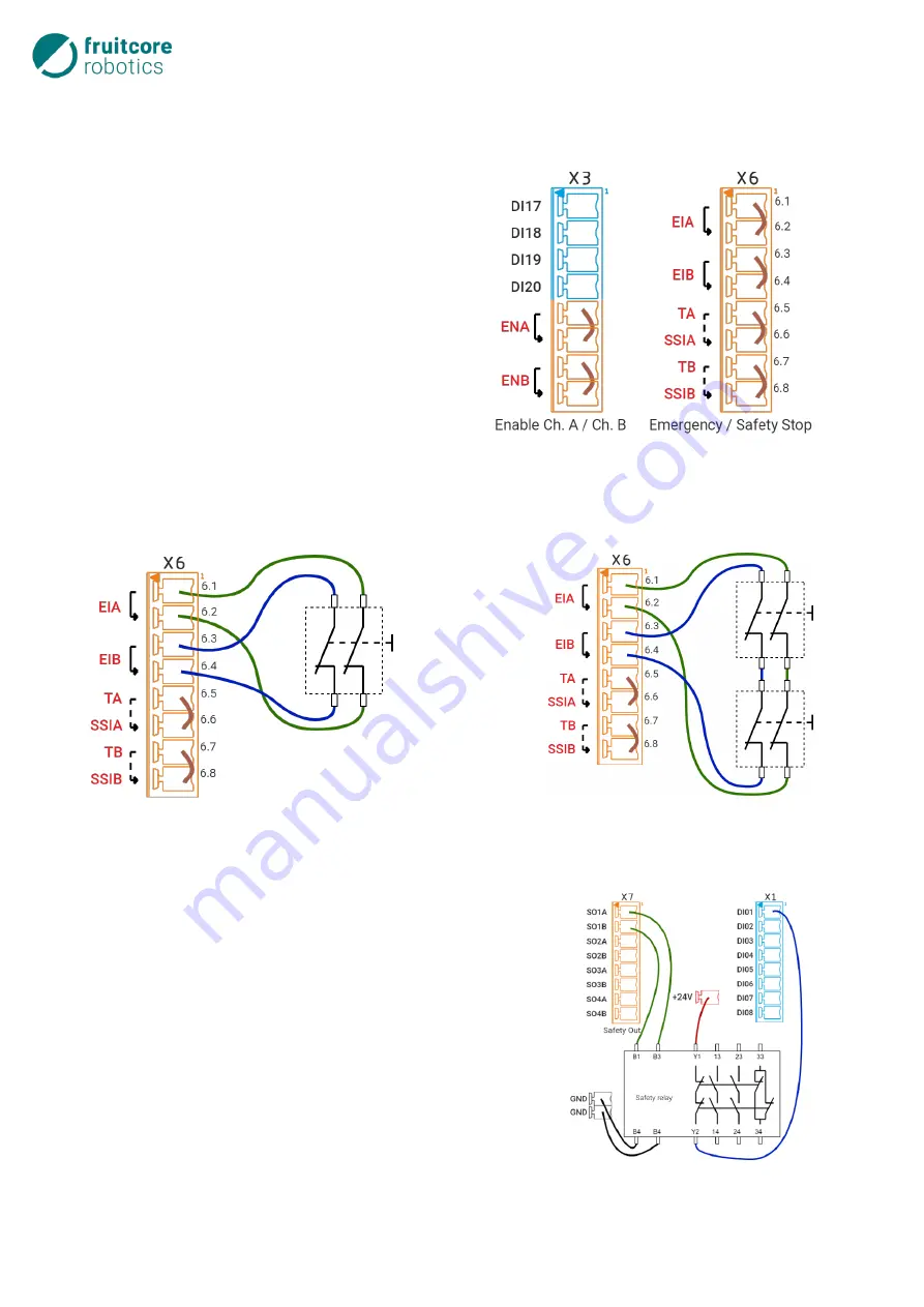
Wiring Examples of Safety-critical Inputs/Outputs
This subsection provides examples of the wiring of digital interfaces on the horstCONTROL. Other exam-
ples can be found on horstCOSMOS.
6.4.8.1
Standard Safety Configuration
In the delivery state, the control system is configured
for sole operation of the robot. This means that no fur-
ther customized, safety-critical devices are connected
to the control system. For the mandatory functions
−
Emergency stop
−
Safety stop
−
Enabling switch
bridges are plugged into connectors X3 and X6 for this
purpose, see adjacent figure.
6.4.8.2
Additional Emergency Stop Buttons
One or more additional emergency stop buttons should
be used, which cause the robot to stop in an emergency. The adjacent figures clarify the connection of
further two-channel emergency stop buttons, which are series-connected to the button on the horst-
PANEL.
6.4.8.3
Safety Relay
A safety relay should be safely actuated and contactor monitoring
should be set up. The two inputs of the relay are connected to
channel A and channel B of e.g. Safety Out 1. Contactor monitor-
ing can be achieved by routing a +24 V signal via the feedback
current path to a general digital input.
Fig. 6-17: Connection of external emergency stop button
Fig. 6-18: Connection of several external emergency
stop buttons
Fig. 6-19: Connection of a safety relay
Fig. 6-16: Standard safety configuration
Summary of Contents for HORST900
Page 3: ...III ...


