13 Stopping Distances and Stopping Times
70
13.2
Stopping Distances and Stopping Times
The stopping distance is the distance covered by the TCP after the stop signal is triggered and until a
complete standstill is reached.
DANGER!
A speed update or load change can result in longer braking distances and unexpected colli-
sions with people or other objects and machines.
Always adjust safety distances to the corresponding stopping distances.
ATTENTION!
Danger of damage to robot or property.
A collision can cause significant damage to the robot system or any surrounding objects.
The stopping time is the time that passes from the stop signal being triggered until the robot reaches a
complete standstill. The stopping distances and stopping times have been determined for the three main
axes Axis 1, Axis 2 and Axis 3.
The table shows the stopping distances and stopping times when triggered by an emergency stop signal
at speed 100 % with
horstFX performance
. Without
horstFX performance
the stopping time is the same
and the stopping distances are correspondingly shorter.
Average
stopp
ing distance (°)
Average
stopping time (s)
Load 0 kg
Load 5 kg
Load 0 kg
Load 5 kg
Axis 1
118.7
82.9
0.81
0.80
Axis 2
51.6
30.0
0.78
0.79
Axis 3
58.3
45.6
0.40
0.81
Table 13-1: Stopping distances and times with horstFX performance
The braking time is a correcting variable defined by the control system. The stopping distance is therefore
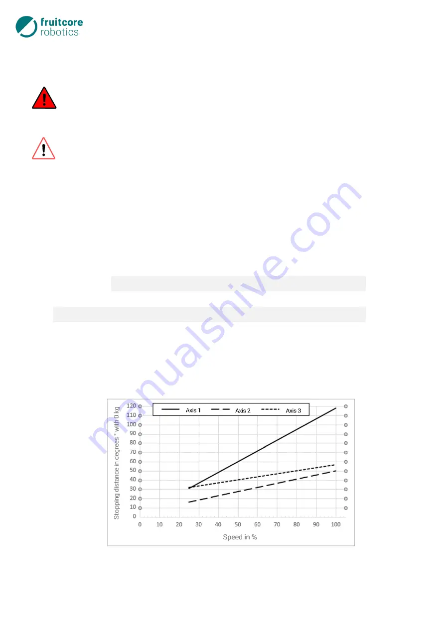
independent of the respective applied load or the load of the robot arm. The influence of speed on the
stopping distance can be seen in the figure below.
Fig. 13-1: Stopping distances of the main axes with 0 kg load capacity
Summary of Contents for HORST900
Page 3: ...III ...


