background image

Frymaster L.L.C., 8700 Line Avenue 71106, 5489 Campus Drive 71129

P.O. Box 51000, Shreveport, Louisiana 71135-1000

PHONE 318-865-1711         FAX 318-219-7135

PRINTED IN THE UNITED STATES          SERVICE HOTLINE 1-800-24-FRYER

    819-5551A  10/00

SERVICE MANUAL

UNIVERSAL HOLDING CABINET (UHC)

MANUFACTURED BY

P.O. BOX 51000

SHREVEPORT, LOUISIANA

71135-1000

PHONE 1-318-865-1711

1-800-24 FRYER           

Universal Holding Cabinet                                                                                                                           1-1
Power Up                                                                                                                                                      2-1
Operational Overview                                                                                                                                   3-1
Operator Mode                                                                                                                                              4-1
Timer Operation                                                                                                                                            5-1
Cook More Prompts                                                                                                                                      6-1
Switching Between Breakfast. Lunch, Clean Mode and Slot Off                                                                 7-1
Slot Temperature Display                                                                                                                             8-1
Temperature Alarms                                                                                                                                     9-1
Product Selection                                                                                                                                        10-1
Program Mode                                                                                                                                            10-1
Page Selection                                                                                                                                             10-2
Meal Selection                                                                                                                                            10-3
Exiting Program Mode                                                                                                                               10-5
Example of Production Selection Change                                                                                                  10-6
Entering and Editing Product Information                                                                                                  11-1
Entering Password                                                                                                                                      11-1
Entering Product Name                                                                                                                               11-1
Entering Product Holding Time                                                                                                                  11-3
Enter Meal Usage                                                                                                                                       11-4
Display Adjustments                                                                                                                                   12-1
Change Display Time                                                                                                                                 12-1
Change Display Intensity                                                                                                                            12-1
Change F° to C°


12-1

Troubleshooting Guide                                                                                                                               13-1
Diagnostic Tests                                                                                                                                          14-1
Service Procedures                                                                                                                                      15-1
Parts Lists, Exploded Views                                                                                                                       16-1
Wiring Diagram                                                                                                                                          17-1

Appendices

                                                                                                                                                18-1

Appendix A:

 Food Item Default Settings                                                                                                  18-1

Appendix B:

 Cleaning and Preventive Maintenance                                                                                 18-2

Appendix C:

 RTD Resistance Chart                                                                                                          18-4

Appendix D: 

SOC for Universal Holding Cabinet                                                                                    18-5

Appendix E: 

Production Charts                                                                                                                  18-6

Appendix F:

 Quick Reference Guide                                                                                                        18-7

Appendix G:

 Typical Setups/Stacked Arrangements                                                                                18-8

Summary of Contents for Universal Holding Cabinet

Page 1: ...Program Mode 10 1 Page Selection 10 2 Meal Selection 10 3 Exiting Program Mode 10 5 Example of Production Selection Change 10 6 Entering and Editing Product Information 11 1 Entering Password 11 1 En...

Page 2: ...also pay straight time labor costs to replace the part plus up to 100 miles 160 km of travel 50 miles 80 km each way 1 1 2 Parts Return A All defective in warranty parts must be returned to a Frymaste...

Page 3: ...oes not supply these accessory items To speed up your order the following information is required Model Number_____________________________________ Serial Number_____________________________________ V...

Page 4: ...ucts McNuggets McChicken Filet O Fish etc Remember this important procedure when storing fried products Fried products are to be placed on the wire rack The rack should be placed on a crumb tray No tr...

Page 5: ...n handling the cabinet or tilting the unit to from the floor to install the legs Maneuvering the cabinet should be accomplished by at least two people A Carefully place the Universal Holding Cabinet o...

Page 6: ...Y GROUNDED THREE PRONG RECEPTACLE DO NOT CUT OR REMOVE THE GROUNDING PRONG FROM THIS PLUG B Plug the Universal Holding Cabinet into the power source C Place the power switch in the ON position All con...

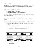
Page 7: ...f Distribution SPOD cabinet has only a front controller for each slot UHC Controller Front Display and Keypad Timer keys Left Center and Right start and stop the timer associated with each tray positi...

Page 8: ...s product selection and holding time status by changing the display intensity The Use First Display indicates the product with the least amount of holding time remaining There are two levels of displa...

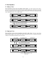
Page 9: ...AUS SAUS Press TIMER key to start a timer Active display alternately indicates holding time and product selection 5 2 Stopping A Timer Press the Timer key above the slot position to turn off an active...

Page 10: ...ng ENTER PAGE MENU Timed Out Timer Next Shortest Time Inactive Timer 00 00 00 00 SAUS SAUS Press TIMER key to turn of audible alarm ENTER PAGE MENU SAUS SAUS SAUS SAUS SAUS SAUS Display returns to ina...

Page 11: ...ays the remaining holding time and product mnemonic The Timer Display Time TIMR TIME and Product Display Time PROD TIME values determine how long in seconds that each message is displayed Default sett...

Page 12: ...edgment of the audible alarm is required It occurs only to get the attention of the operator ENTER PAGE MENU muff muff muff muff 30 30 30 30 cook cook cook cook Cook More After accessing the Cook More...

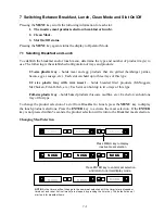
Page 13: ...up to two trays of this type Full size plastic tray holds baked products biscuits muffins etc Each slot can hold one tray of this type To change the product selection of a slot from Breakfast to Lunc...

Page 14: ...t to 125 F 52 C Starting Clean Mode To start the Clean Mode press the MENU key to scroll to the Clean Mode message CLN MODE Press the ENTER key to activate the Clean Mode All slots in the cabinet will...

Page 15: ...ss ENTER key to exit Clean Mode and return to normal display mode ENTER PAGE MENU SAUS SAUS SAUS SAUS SAUS SAUS SAUS SAUS SAUS SAUS SAUS SAUS 7 3 Slot On Off To turn a slot off press the MENU key to s...

Page 16: ...he temperature is within normal operating limits If the ENTER key is not pressed within 5 seconds the slot returns to the SLOT OFF status ENTER PAGE MENU 15 15 15 15 OFF OFF OFF OFF SLOT SLOT SLOT SLO...

Page 17: ...US SAUS SAUS SAUS SAUS SAUS SAUS Press temperature key to display top plate temperature TEMP TEMP TEMP TEMP MENU TOP TOP TOP TOP 160 160 160 160 Press temperature key to display bottom plate temperatu...

Page 18: ...rm message will read either SLOT TEMP HIGH or SLOT TEMP LOW To turn off the audible alarm press any Timer key The displays will alternately display the product selection and the alarm message until th...

Page 19: ...ue above or below the operating limit 90 F 32 C to 250 F 121 C of the slot The alarm message is SENS ALRM To turn off the audible alarm press any Timer key The alarm message will be displayed until th...

Page 20: ...display indicates a sensor error Service will be required to correct this condition 9 5 2 LLLL LLLL in the display indicates either a sensor error or a slot that is below 50 F 10 C Allow the slot to...

Page 21: ...for each display within a slot Full size plastic tray Since each slot can accommodate one tray the center display will be used to establish product parameters The center display establishes the produc...

Page 22: ...G Press the PAGE key to scroll to slot page selections 1 1 1 1 ENTER PAGE MENU SLOT SLOT SLOT SLOT Press ENTER key to turn slot ON and return to normal display mode ENTER PAGE MENU slot slot slot slot...

Page 23: ...NTER PAGE MENU lnch lnch lnch lnch left left left left 10 1 10 1 10 1 10 1 ENTER PAGE MENU lnch lnch lnch lnch cent cent cent cent 10 1 10 1 10 1 10 1 ENTER PAGE MENU lnch lnch lnch lnch rght rght rgh...

Page 24: ...left saus saus saus saus bfst bfst bfst bfst Press Up Down arrow keys to scroll product selections left left left left MENU bfst bfst bfst bfst roun roun roun roun MENU bfst bfst bfst bfst left left...

Page 25: ...slot 3 3 3 3 Press the MENU key to scroll meal selection and tray position saus saus saus saus ENTER PAGE MENU bfst bfst bfst bfst left left left left Press the MENU key to scroll meal selection and t...

Page 26: ...ering password Saus Saus Saus Saus ENTER PAGE MENU SAUS SAUS SAUS SAUS saus saus saus saus Press and hold MENU key for 5 seconds to enter Program Mode ENTER PAGE MENU prog prog prog prog mode mode mod...

Page 27: ...d prod prod x x x x ENTER PAGE MENU prod prod prod prod name name name name x x x x ENTER PAGE MENU prod prod prod prod name name name name xx xx xx xx ENTER PAGE MENU prod prod prod prod name name na...

Page 28: ...TER PAGE MENU time time time time 25 25 25 25 xxy xxy xxy xxy Press PAGE key to scroll to the Temp page ENTER PAGE MENU temp temp temp temp page page page page Press MENU key to scroll to product top...

Page 29: ...ct meal selection Press Up Down arrow key to select BFST 11 6 Enter Cook Time MENU xxy xxy xxy xxy meal meal meal meal all all all all Press PAGE key to scroll to the Cook Page ENTER PAGE MENU cook co...

Page 30: ...the intensity levels used for product status may be adjusted as follows Press and hold MENU key for 5 seconds Press PAGE key to scroll to View Page Press MENU key to scroll to the Security Lock Press...

Page 31: ...2 Blown 20 amp fuse 3 Defective power switch 4 Broken or improper wire connection Check CN2 5 Defective transformer 6 Defective master control board Are timers operating Operation Normal 1 Broken or...

Page 32: ...ted wires 3 Apply power and measure AC voltage to board on connector CN1 Correct measurement is 16 volts across the two outside connectors and 8 volts from either outside connector to the center conne...

Page 33: ...lot off measure the slot temperature If the slot is heating it is miswired or the master control board is defective shorted triac 14 6 Display Driver Display Isolation Test 1 On stand alone units disc...

Page 34: ...hart on Page 18 5 for resistance at different temperatures If either resistance is incorrect replace the heater plate 14 8 Display Meanings 1 SLOT TEMP HIGH OR SLOT TEMP LOW and no audible alarm This...

Page 35: ...r to remove the four cabinet screws holding the equipment shelf in place The screws are located on each side of the unit near the top corners of the inner panel 6 Use 5 16 nut driver to remove the two...

Page 36: ...s See Appendix B 12 Reconnect power turn the power switch to the ON position and reprogram the controllers as necessary to the desired menu selections 15 2 Replacing Membrane Switch Switches Perform s...

Page 37: ...cts the membrane switch to the display board by gently pulling the cable from the connector on the display board Fig 11 Note Early production units prior to S N 9703 had the membrane switch soldered t...

Page 38: ...y With the cabinet s sides still off disconnect CN2 connector from the display driver s to be tested Fig 14 Plug unit in and turn on power switch The selected display will show Disp Test Mode Press ea...

Page 39: ...ull turn but do not remove 3 Remove wire wraps from wiring harness holding heater and control wires for affected slot 4 Lifting slightly carefully slide the malfunctioning slot out of the cabinet Do n...

Page 40: ...the four spacer setscrews along the edges of the plate Fig 19 4 Slide the malfunctioning plate out of the spacer Fig 20 5 Slide the replacement plate into position Make sure the plate is inserted squ...

Page 41: ...tion 1 806 8162SP 1 Bottom Pan Assembly 2 806 7904 1 Pan Base 3 See Page 16 2 4 Slot Assembly 4 910 4876SP 2 Cabinet Side 4 slot unit Right and Left Not Shown 106 0266 2 Cabinet Side 2 slot unit Right...

Page 42: ...10 807 3308 1 ON OFF Switch 11 806 8654 SP 1 Front Fascia 12 900 4946 2 Slide Bracket 13 816 0265 4 Bushing 75 ID Snap in 14 See next page 1 Shelf Assembly 15 807 3238 1 Power Cord Strain Relief 16 82...

Page 43: ...zzer Kit 3 807 2460 1 Transformer 4 807 2665 2 Exhaust blower 5 807 2812 1 Terminal block 6 807 2819 2 Fuse 20 amp 7 807 2820 1 Fuse block 8 809 0094 2 Screw 6 32 x 3 8 9 826 1366 2 Nut hex keps 10 80...

Page 44: ...ion 1 807 2767 1 Bead Shield CE only 2 807 2766 1 Power Line Filter CE only 3 807 2769 1 Power Transformer CE only 16 4 Pre 1997 Components 1 2 3 Item Part number Quantity Description 1 807 2278 2 20...

Page 45: ...play Not for pre S N 9703 3 807 3310 1 Display Assembly Rear Slot All including pre S N 9703 Not Shown 807 3312 1 Membrane Switch Rear Display Not for pre S N 9703 4 809 0593 8 Screw set 6 x 1 2 5 809...

Page 46: ...17 1 17 Wiring Diagram UHC...

Page 47: ...con CBAC BFST 175 F 79 C bottom plate 30 175 F 79 C top plate English Muffins MUFF BFST 175 F 79 C bottom plate 20 175 F 79 C top plate Biscuits BISC BFST 175 F 79 C bottom plate 60 185 F 85 C top pla...

Page 48: ...2 on Pages 7 2 7 3 Note Do not use McD Sink Sanitizer HCS to clean the exterior of the Universal Holding Cabinet 2 Let the unit cool until SAFE to CLN is displayed Use brush to remove any remaining b...

Page 49: ...program mode by pressing the Menu key for at least five seconds Press the page key until View____PAGE appears in the slot controller display Press the Menu key until SECR Lock _ _ _ _ is displayed Ent...

Page 50: ...to be serviced is the bottom unit of a stacked arrangement use a 5 16 socket driver and remove the four screws holding the equipment shelf in place The screws are located on each side of the unit near...

Page 51: ...8 125 120 036 51 66 130 121 104 54 44 135 122 172 57 22 140 123 239 60 00 145 124 304 62 77 150 125 369 65 55 155 126 433 68 33 160 127 496 71 11 165 128 559 73 88 170 129 620 76 66 175 130 680 79 44...

Page 52: ...scrambles grilled chicken and 4 to 1 patties can be stacked up to three high See Appendix G Page 18 9 The procedure for the Universal Holding Cabinet when used for BISCUITS is as follows After the bis...

Page 53: ...WN arrow keys to select the product RESULT 10 1 10 1 10 1 10 1 lnch lnch lnch lnch left left left left left left left left 4 1 4 1 4 1 4 1 lnch lnch lnch lnch Continue to press the UP and DOWN keys to...

Page 54: ...UGG NONE NUGG NUGG NONE McCK McCK NONE McCK FISH NONE FISH Left Center Right Left Center Right Left Center Right Left Center Right Typical Breakfast Setup Left Cabinet SAUS SAUS SAUS ROUN ROUN ROUN FO...

Page 55: ...18 9 Stacked Arrangements 10 1 Meat Patties Recommended Stack Normal Volume 9 3 Recommended Stack Ultra High Volume 18 6...

Reviews: