background image

V3.0

COMMUTATEURS L2+ GIGABIT GÉRÉS

MANAGED L2+ GIGABIT SWITCHES

MANAGED L2+ GIGABIT SWITCHES

Quick Start Guide 

Quick-Start Anleitung 
Guide de Démarrage Rapide

S3900-24F4S

1

2

3

4

5

6

7

8

9

10

11

12

13

14

15

16

17

18

19

20

21

22

23

24

21

22

23

24

25

26

27

28

SYS

PWR

CONSOLE

MGT

S3900-24T4S

1

2

3

4

5

6

7

8

9

10

11

12

13

14

15

16

17

18

19

20

21

22

23

24

25

25

26

26

27

28

27

28

SYS

PWR

RESET

CONSOLE

MGT

Summary of Contents for S3900 Series

Page 1: ...rt Guide Quick Start Anleitung Guide de D marrage Rapide S3900 24F4S 1 2 3 4 5 6 7 8 9 10 11 12 13 14 15 16 17 18 19 20 21 22 23 24 21 22 23 24 25 26 27 28 SYS PWR CONSOLE MGT S3900 24T4S 1 2 3 4 5 6...

Page 2: ...and use them to protect idle optical ports S3900 24F4S S3900 48T4S S3900 24T4S S3900 24F4S 1 2 3 4 5 6 7 8 9 10 11 12 13 14 15 16 17 18 19 20 21 22 23 24 21 22 23 24 25 26 27 28 SYS PWR CONSOLE MGT S...

Page 3: ...nnection SFP ports for 1 10G connection An out of band Ethernet management port An RJ45 console port for serial management S3900 24T4S S3900 24F4S 1 2 3 4 5 6 7 8 9 10 11 12 13 14 15 16 17 18 19 20 21...

Page 4: ...tion RESET Restart Press and release the Reset button quickly Restore to Factory Default Settings Press and hold the Reset button for more than ten seconds Back Panels S3900 24T4S S3900 24T4S S3900 48...

Page 5: ...n Data is being transmitted or received No device is connected to the corresponding port A device is connected to the corresponding port but no activity S3900 24T4S S3900 24F4S S3900 48T4S S3900 24F4S...

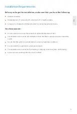
Page 6: ...40 C Installation Requirements Phillips screwdriver Standard sized 19 wide rack with a minimum of 1U height available Category 5e or higher RJ 45 Ethernet cables for connecting network devices The in...

Page 7: ...the mounting brackets to the two sides of the switch with six M4 screws 25 25 26 26 27 28 27 28 SYS PWR RESET CONSOLE MGT Desk Mounting 1 Attach four rubber pads to the bottom 2 Place the chassis on...

Page 8: ...a proper earth ground such as the rack in which the switch is mounted 2 Secure the grounding lug to the grounding point on the switch back panel with the washers and screws Grounding the Switch 90 26...

Page 9: ...ct the other end of the Ethernet cable to the RJ45 port of the switch 1 Plug the AC power cord into the power port on the back of the switch 2 Connect the other end of the power cord to an AC power so...

Page 10: ...the Console Port 1 Insert the RJ45 connector into the RJ45 console port on the front of the switch 2 Connect the DB9 female connector of the console cable to RS 232 serial port on the computer 18 19 2...

Page 11: ...hes in the series can be physically stacked using optical fiber cables connected to SFP transceivers or 10G Direct Attach Cables DAC Only the last two SFP ports on the switch can be used for physical...

Page 12: ...gs assigned automatically if your network supports this capability Otherwise you need to ask your network administrator for the appropriate IP settings Internet Protocol Version 4 TCP IPv4 Properties...

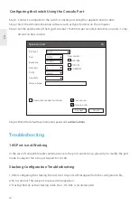
Page 13: ...o adapt or force the port speed to 1G 10G 10G Port is not Working Step 1 Connect a computer to the switch s console port using the supplied console cable Step 2 Start the terminal simulation software...

Page 14: ...e switch 3 Check if the corresponding service is enabled Connecting the Switch Remotely Unsuccessfully The Port is not Working the LED Indicator is Off 1 Ensure the switch ports are in the no shutdown...

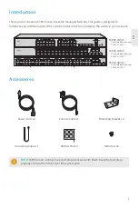
Page 15: ...taubschutzkappen geliefert Bewahren Sie die Kappen ordnungsgem auf und verwenden Sie sie um ungenutzte optische Anschl sse zu sch tzen S3900 24F4S S3900 48T4S S3900 24T4S S3900 24F4S 1 2 3 4 5 6 7 8 9...

Page 16: ...ndung SFP Ports f r 1 10G Verbindung Ein Out of Band Ethernet Management Anschluss Ein RJ45 Konsolenanschluss f r die serielle Verwaltung S3900 24T4S S3900 24F4S 1 2 3 4 5 6 7 8 9 10 11 12 13 14 15 16...

Page 17: ...T Neustart Dr cken Sie die Reset Taste schnell und lassen Sie sie los Auf Werkseinstellungen zur cksetzen Dr cken und halten Sie die Reset Taste l nger als zehn Sekunden R ckseite S3900 24T4S S3900 24...

Page 18: ...Es werden Daten gesendet oder empfangen Kein Ger t ist mit dem entsprechenden Anschluss verbunden Ein Ger t ist mit dem entsprechenden Anschluss verbunden aber keine Aktivit t S3900 24T4S S3900 24F4S...

Page 19: ...t Installationsanforderungen Kreuzschlitzschraubendreher 19 Rack in Standardgr e mit einer Mindesth he von 1 HE RJ 45 Ethernet Kabel der Kategorie 5e oder h her f r den Anschluss von Netzwerkger ten D...

Page 20: ...ie Montagehalterungen mit acht M4 Schrauben an beiden Seiten des Switches 25 25 26 26 27 28 27 28 SYS PWR RESET CONSOLE MGT Bodenmontage 1 Bringen Sie vier Gummipads an der Unterseite an 2 Stellen Sie...
Page 21: ...ete Erdung an z B an das Rack in dem der Switch montiert ist 2 Befestigen Sie die Erdungslasche mit den Unterlegscheiben und Schrauben am Erdungspunkt an der R ckwand des Switches Erdung des Switch 90...

Page 22: ...e Ende des Ethernet Kabels an den RJ45 Port des Switches an 1 Stecken Sie das Netzkabel in den Netzanschluss auf der R ckseite des Switches 2 Schlie en Sie das andere Ende des Netzkabels an eine Netzs...

Page 23: ...Konsolen Ports 1 Stecken Sie den RJ45 Stecker in den RJ45 Konsolenanschluss an der Vorderseite des Switches 2 Verbinden Sie die DB9 Buchse des Konsolenkabels mit dem seriellen RS 232 Anschluss des Co...

Page 24: ...der Die Switches der Serie k nnen mithilfe von Glasfaserkabeln die mit SFP Transceivern verbunden sind oder 10G Direct Attach Cables DAC physisch gestapelt werden Nur die letzten beiden SFP Ports des...

Page 25: ...You can get IP settings assigned automatically if your network supports this capability Otherwise you need to ask your network administrator for the appropriate IP settings Internet Protocol Version...

Page 26: ...igkeit auf 1G 10G zu erzwingen 10G Port funktioniert nicht Schritt 1 Schlie en Sie einen Computer ber das mitgelieferte Konsolenkabel an den Konsolenanschluss des Switches an Schritt 2 Starten Sie ein...

Page 27: ...Switches 3 Pr fen Sie ob der entsprechende Dienst aktiviert ist Fehlgeschlagener Remote Anschluss des Switches Der Port funktioniert nicht die LED Anzeige ist aus 1 Vergewissern Sie sich dass sich die...

Page 28: ...0 sont quip s de bouchons anti poussi re Conservez soigneusement ces bouchons et utilisez les pour prot ger les ports optiques inactifs S3900 24F4S S3900 48T4S S3900 24T4S S3900 24F4S 1 2 3 4 5 6 7 8...

Page 29: ...FP pour connexion 1G Ports SFP pour connexion 1 10G Port de gestion Ethernet hors bande Port de console RJ45 pour la gestion S3900 24T4S S3900 24F4S 1 2 3 4 5 6 7 8 9 10 11 12 13 14 15 16 17 18 19 20...

Page 30: ...ez et rel chez rapidement le bouton Reset R tablir les Param tres de D faut d Usine Appuyez et maintenez la touche Reset pendant plus de dix secondes Panneaux Post rieurs S3900 24T4S S3900 24T4S S3900...

Page 31: ...um Les donn es sont en cours de transmission ou de r ception Aucun appareil n est connect au port correspondant Un appareil est connect au port correspondant mais il n y a aucune activit S3900 24T4S S...

Page 32: ...ns d Installation Tournevis Phillips Rack standard de 19 de large avec une hauteur minimale de 1U disponible C bles Ethernet RJ 45 de cat gorie 5e ou sup rieure pour la connexion de dispositifs de r s...

Page 33: ...de montage aux deux c t s du commutateur l aide de six vis M4 25 25 26 26 27 28 27 28 SYS PWR RESET CONSOLE MGT Montage sur Support 1 Fixez quatre blocs en caoutchouc sur la base 2 Placez le ch ssis...

Page 34: ...elle que le rack sur lequel le commutateur est install 2 Fixez la prise au point de mise la terre sur le panneau post rieur du commutateur l aide des rondelles et vis Mise Terre du Commutateur 90 264V...

Page 35: ...le Ethernet au port RJ45 du commutateur 1 Branchez le c ble d alimentation CA dans le port d alimentation situ l arri re du commutateur 2 Branchez l autre extr mit du c ble d alimentation une source d...

Page 36: ...le connecteur RJ45 dans le port RJ45 de la console situ sur le panneau frontal du commutateur 2 Branchez le connecteur femelle DB9 du c ble de la console au port s rie RS 232 de l ordinateur 18 19 20...

Page 37: ...ateurs de la s rie peuvent tre physiquement empil s l aide de c bles en fibre optique connect s des modules SFP ou de C bles Connexion Directe DAC 10G Seuls les deux derniers ports SFP du commutateur...

Page 38: ...automatically if your network supports this capability Otherwise you need to ask your network administrator for the appropriate IP settings Internet Protocol Version 4 TCP IPv4 Properties Use the foll...

Page 39: ...du port pour adapter ou forcer la vitesse du port 1G 10G Le port 10G ne fonctionne pas tape 1 Connectez un ordinateur au port de console du commutateur l aide du c ble de console fourni tape 2 D marre...

Page 40: ...est activ Connexion distance du commutateur sans succ s Le port ne fonctionne pas l indicateur LED est teint 1 Assurez vous que les ports de commutation sont en tat de non arr t No Shutdown 2 V rifie...

Page 41: ...he user is encouraged to try to correct the interference by one or more of the following measures Reorient or relocate the receiving antenna Increase the separation between the equipment and receiver...

Page 42: ...mit tserkl rung finden Sie unter www fs com de company quality_control html FS COM GmbH hereby declares that this device is in compliance with the Directive 2014 30 EU and 2014 35 EU A copy of the EU...

Reviews: