background image

DE

23


3

26

4

Breakout

1

2

3

26

25

4

Breakout

Konfigurieren des Switches

Konfigurieren des Switches über das webbasierte Interface

Schritt 1: Schließen Sie den Computer mit dem Netzwerkkabel an den Verwaltungsport des Switches an
Schritt 2: Stellen Sie die IP-Adresse des Computers auf 192.168.1.x ein. ("x" ist eine beliebige Zahl von 2 
bis 254.). Setzen Sie die Subnetzmaske des Computers auf 255.255.255.0.

Schritt 3: Öffnen Sie einen Browser, geben Sie 

http://192.168.1.1

 ein, und geben Sie den 

Standardbenutzernamen und das Passwort (

admin/admin

) ein. 

Schritt 4: Klicken Sie auf Sign in, um die webbasierte Konfigurationsseite anzuzeigen.

?

x

OK

Cancel

General

IP address:

Subnet mask :

D efault gateway :

Yo u   c a n   g e t   I P   s e t t i n g s   a s s i g n e d   a u t o m a t i c a l l y   i f   y o u r   n e t w o r k  

s u p p o r t s   t h i s   c a p a b i l i t y.   O t h e r w i s e ,   y o u   n e e d   t o   a s k   y o u r   n e t w o r k

a d m i n i s t r a t o r   f o r   t h e   a p p r o p r i a t e   I P   s e t t i n g s .

Internet  Protocol Version  4  ( TCP/IPv4) Proper ties

Use the following IP address:

Obtain an IP address automatically

Preferred DNS server:

Alternate DNS server:

Validate settings upon exit

A d v a n c e d . . .

.       .       . 2

1

168

192

0

255

255

255

.       .       .

.       .       .

.       .       .

.       .       .

Obtain DNS ser ver address automatically

Use the following DNS ser ver addresses:

Summary of Contents for S5850-24XMG

Page 1: ... de Démarrage Rapide S5850 24XMG MANAGED L3 ENTERPRISE SWITCH Managed L3 Enterprise Switch SWITCH MANAGEABLE L3 POUR ENTREPRISE SYS ID MGMT CON MGMT S5850 24X MG 2 1 4 3 6 5 8 7 10 9 12 11 14 13 16 15 18 17 20 19 22 21 24 23 1 2 3 26 100G 25 4 Breakout ...

Page 2: ... and describes how to deploy the switch in your network S5850 24XMG SYS ID MGMT CON MGMT S5850 24XMG 2 1 4 3 6 5 8 7 10 9 12 11 14 13 16 15 18 17 20 19 22 21 24 23 1 2 3 26 100G 25 4 Breakout Accessories Grounding Cable x1 Console Cable x1 M4 Screw x12 Front Mounting Bracket x2 Power Cord x2 Back Mounting Bracket x2 Sliding Rail x2 ...

Page 3: ...7 10 9 12 11 14 13 16 15 18 17 20 19 22 21 24 23 1 2 3 26 100G 25 4 Breakout CON MGMT USB QSFP28 Front Panel LEDs SYS ID MGMT CON MGMT S5850 24XMG 2 1 4 3 6 5 8 7 10 9 12 11 14 13 16 15 18 17 20 19 22 21 24 23 1 2 3 26 100G 25 4 Breakout SYS MGMT ID RJ45 QSFP28 Off Blue Amber Off Green LEDs State Description ID indication function enable ID SYS MGMT ID indication function disable System is running...

Page 4: ...rt is linked at 40 100G Off L Blinking Green Amber Blinking Amber Off Port is linked at 10 25G Packets are receiving or transmitting at 10 25G Port is not linked Back Panel 4 Hot swappable Fans 2 Hot swappable Power Supplies Grounding Point Installation Requirements Phillips screwdriver Before you begin the installation make sure that you have the followings Standard sized 19 wide rack with a mini...

Page 5: ...site must be well ventilated Ensure that there is adequate air flow around the switch Be sure that the switch is level and stable to avoid any hazardous conditions Mounting the switch Desk Mounting 1 Attach four rubber pads to the bottom 2 Place the chassis on a desk SYS ID MGMT CON MGMT S5850 24XMG 2 1 4 3 6 5 8 7 10 9 12 11 14 13 16 15 18 17 20 19 22 21 24 23 1 2 3 26 100G 25 4 Breakout SYS ID M...

Page 6: ... the two sides of the switch with screws 2 Push back mounting brackets onto the silding rails 18 17 20 19 22 21 24 23 1 2 3 26 100G 25 4 Breakout SYS ID MGMT CON MGMT S5850 24X MG 2 1 4 3 6 5 8 7 10 9 12 11 14 13 16 15 18 17 20 19 22 21 24 23 1 2 3 26 100G 25 4 Breakout ...

Page 7: ...onnection must not be removed unless all supply connections have been disconnected 1 Connect one end of the grounding cable to a proper earth ground such as the rack in which the switch is mounted 2 Secure the grounding lug to the grounding point on the back panel of the switch with the washer and screws ...

Page 8: ... RJ45 Ports 1 Connect an Ethernet cable to the RJ45 port of a computer printer network storage or other network devices 2 Connect the other end of the Ethernet cable to the RJ45 port of the switch WARNING Do not install power cable while the power is on 10 9 12 11 14 13 16 15 18 17 20 19 22 21 24 23 1 2 3 26 100G 25 4 Breakout SYS ID MGMT CON MGMT S5850 24XMG 2 1 4 3 6 5 8 7 ...

Page 9: ...FP28 port 2 Connect a fiber optic cable to the transceiver then connect the other end of the cable to another fiber device 3 Or directly connect DAC AOC cable to the QSFP28 port Connecting the QSFP28 Ports CAUTION Laser beams will cause eye damage Do not look into bores of optical modules or optical fibers without eye protection ...

Page 10: ...puter Connecting the MGMT Port 1 Connect one end of a standard RJ45 Ethernet cable to a computer 2 Connect the other end of the cable to the MGMT port on the switch Connecting the Management Ports SYS ID MGMT CON MGMT S5850 24XMG 2 1 4 3 6 5 8 7 10 9 12 11 14 13 16 15 18 17 20 19 22 21 24 23 SYS ID MGMT CON MGMT S5850 24X MG 2 1 4 3 6 5 8 7 10 9 12 11 14 13 16 15 18 17 20 19 22 21 24 23 ...

Page 11: ... admin admin Step 4 Click sign in to display the web based configuration page x OK Cancel General IP address Subnet mask Default gateway You can get IP settings assigned automatically if your network suppor ts this capability O ther wise you need to ask your network administrator for the appropriate IP settings Internet Protocol Version 4 TCP IPv4 Properties Use the following IP address Obtain an ...

Page 12: ...the computer Step 3 Set the parameters of the HyperTerminal 115200 bits per second 8 data bits no parity 1 stop bit and no flow control Step 4 Enter the default username and password admin admin x Quick Connect Protocol Serial Flow Control DTR DSR RTS CTS XON XOFF Save session Show quick connect on startup Open in a tab Connect Cancel COM3 115200 8 None 1 Port Baud rate Data bits Parity Stop bits ...

Page 13: ...le cable 2 Press Ctrl B to enter the Uboot mode 3 Start the system with an empty configuration file with no password Bootrom boot_flash_nopass Bootrom Do you want to revert to the default config file Y N E 1 Make sure the power supply is normal and the console cable is properly connected 2 Check whether the console cable is the right type 3 Check whether the control cable driver is properly instal...

Page 14: ... workmanship we will offer a free return within 30 Days from the day you receive your goods This excludes any custom made items or tailored solutions Warranty This product enjoys 5 years limited warranty against defect in materials or workmanship For more details about warranty please check at https www fs com policies warranty html Return If you want to return item s information on how to return ...

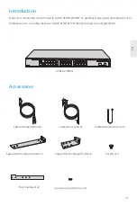
Page 15: ...en Dank dass Sie sich für den S5850 24XMG Switch entschieden haben Diese Anleitung soll Sie mit dem Aufbau des Switches vertraut machen und erklärtt wie Sie den Switch in Ihrem Netzwerk einsetzen Zubehör Erdungskabel x1 Console Kabel x1 M4 Schraube x12 Montagehalterung für die Vorderseite x2 Netzkabel x2 Montagehalterung für die Rückseite x2 Gleitschiene x2 ...

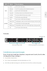
Page 16: ...Verwaltung Ein Ethernet Verwaltungsport Ein USB Port für Software und Konfigurations Backups und Offline Software Upgrades 10 100 1000 2 5G 5G 10GBASE T Ports für Ethernet Verbindung QSFP28 QSFP28 Ports für 40 100G Transceiver LEDs an der Vorderseite Aus Blau Braun Aus Grün LED Status Beschreibung ID Anzeigefunktion ist aktiviert ID SYS MGMT ID Anzeigefunktion ist deaktiviert Das System funktionie...

Page 17: ...0G verbunden Aus L Blinkt Grün Braun Blinkt Braun Aus Der Port ist mit 10 25G verbunden Datenpakete werden mit 10 25G empfangen oder gesendet Der Port ist nicht verbunden Rückseite 4 Hot swap fähige Lüfter 2 Hot Swap fähige Stromversorgungen Erdungspunkt Installationsvoraussetzungen Kreuzschlitzschraubendreher Bevor Sie mit der Installation beginnen vergewissern Sie sich dass Sie über die folgende...

Page 18: ...endem oder tropfendem Wasser starkem Tau und Feuchtigkeit sein Betreiben Sie das Gerät nicht in einem Bereich in dem die Umgebungstemperatur 45 C übersteigt Der Installationsort muss gut belüftet sein Stellen Sie sicher dass um den Switch herum ein ausreichender Luftstrom herrscht Achten Sie darauf dass der Switch eben und stabil steht um gefährliche Bedingungen zu vermeiden Montage des Switches M...

Page 19: ...3 6 5 8 7 10 9 12 11 14 13 16 15 18 17 20 19 22 21 24 23 1 2 3 26 100G 25 4 Breakout DE 18 Rack Montage 1 Befestigen Sie die Montagehalterungen für die Vorderseite und die Gleitschienen mit Schrauben an den beiden Seiten des Switches 2 Schieben Sie die Halterungen zurück auf die Gleitschienen ...

Page 20: ...Der Erdungsanschluss darf erst dann entfernt werden wenn alle Versorgungsanschlüsse getrennt wurden 1 Schließen Sie ein Ende des Erdungskabels an eine geeignete Erdung an z B an das Rack in dem der Switch montiert ist 2 Befestigen Sie die Erdungslasche mit der Unterlegscheibe und den Schrauben am Erdungspunkt auf der Rückseite des Switches ...

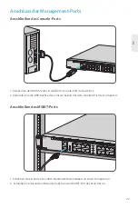
Page 21: ...itches 2 Schließen Sie das andere Ende des Netzkabels an eine Netzstromquelle an Anschließen der RJ45 Ports 1 Schließen Sie ein Ethernet Kabel an den RJ45 Port eines Computers Druckers Netzwerkspeichers oder anderer Netzwerkgeräte an 2 Schließen Sie das andere Ende des Ethernet Kabels an den RJ45 Anschluss an WARNUNG Installieren Sie das Netzkabel nicht wenn der Switch eingeschaltet ist ...

Page 22: ...sfaserkabel an den Transceiver an und verbinden Sie dann das andere Ende des Kabels mit einem anderen Glasfasergerät 3 Oder schließen Sie das DAC AOC Kabel direkt an den QSFP28 Port an Anschließen der QSFP28 Ports VORSICHT Laserstrahlen können Augenschäden verursachen Schauen Sie nicht ohne Augenschutz in die Bohrungen von optischen Modulen oder Glasfasern ...

Page 23: ...MGMT CON MGMT S5850 24X MG 2 1 4 3 6 5 8 7 10 9 12 11 14 13 16 15 18 17 20 19 22 21 24 23 Anschließen des MGMT Ports 1 Schließen Sie ein Ende eines RJ45 Standard Ethernetkabels an einen Computer an 2 Schließen Sie das andere Ende des Kabels an den MGMT Port des Switches an Anschluss der Management Ports SYS ID MGMT CON MGMT S5850 24XMG 2 1 4 3 6 5 8 7 10 9 12 11 14 13 16 15 18 17 20 19 22 21 24 23...

Page 24: ...e den Standardbenutzernamen und das Passwort admin admin ein Schritt 4 Klicken Sie auf Sign in um die webbasierte Konfigurationsseite anzuzeigen x OK Cancel General IP address Subnet mask Default gateway You can get IP settings assigned automatically if your network suppor ts this capability O ther wise you need to ask your network administrator for the appropriate IP settings Internet Protocol Ve...

Page 25: ...omputer Schritt 3 Stellen Sie die Parameter von HyperTerminal ein 115200 Bits pro Sekunde 8 Datenbits keine Parität 1 Stoppbit und keine Flusskontrolle Schritt 4 Geben Sie den Standard Benutzernamen und das Passwort admin admin ein x Quick Connect Protocol Serial Flow Control DTR DSR RTS CTS XON XOFF Save session Show quick connect on startup Open in a tab Connect Cancel COM3 115200 8 None 1 Port ...

Page 26: ...g B um den Uboot Modus aufzurufen 3 Starten Sie das System mit einer leeren Konfigurationsdatei ohne Passwort Bootrom boot_flash_nopass Bootrom Wollen Sie zur Standard Konfigurationsdatei zurückkehren Y N E 1 Vergewissern Sie sich dass die Stromversorgung normal ist und das Console Kabel richtig angeschlossen ist 2 Prüfen Sie ob das Console Kabel der richtige Typ ist 3 Prüfen Sie ob der Steuerkabe...

Page 27: ... sind eine kostenlose Rückgabe innerhalb von 30 Tagen nach Erhalt der Ware anbieten Dies gilt nicht für Sonderanfertigungen oder maßgeschneiderte Lösungen Garantie Für dieses Produkt gilt eine beschränkte Garantie von 5 Jahren auf Material und Verarbeitungsfehler Weitere Einzelheiten zur Garantie finden Sie unter https www fs com de policies warranty html Rückgabe Wenn Sie einen oder mehrere Artik...

Page 28: ... vous remercions d avoir choisi le switch S5850 24XMG Ce guide est conçu pour vous puissiez vous familiariser avec la configuration du switch et décrit comment procéder à son déploiement Accessoires Câble de Mise à la Terre x1 Câble de Console x1 Vis M4 x12 Support de Montage Frontal x2 Câble d Alimentation x2 Support de Montage Arrière x2 Rail Coulissant x2 ...

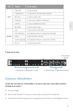
Page 29: ...on Ethernet QSFP28 Ports QSFP28 pour modules 40 100G Indicateurs LED du Panneau Frontal SYS ID MGMT CON MGMT S5850 24XMG 2 1 4 3 6 5 8 7 10 9 12 11 14 13 16 15 18 17 20 19 22 21 24 23 1 2 3 26 25 4 Breakout SYS MGMT ID RJ45 QSFP28 Éteint Bleu Jaune Éteint Vert LED Statut Description Activation de la fonction d indication de l ID ID SYS MGMT Désactivation de la fonction d indication de l identité L...

Page 30: ...ignotant Jaune Jaune Clignotant Éteint Le port est relié à 10 25G Les paquets sont reçus ou transmis à 10 25G Le port n est pas relié Panneau Arrière 4 Ventilateurs remplaçables à chaud 2 Aalimentations remplaçables à chaud Point de Mise à la Terre Exigences d Installation Tournevis Phillips Avant de commencer l installation assurez vous que vous disposez des éléments suivants Rack de taille stand...

Page 31: ...ux Le site d installation doit être exempt de fuites d eau et d humidité Ne pas installer l appareil dans un endroit où la température ambiante dépasse 45 C Le site d installation doit être bien ventilé Veillez à ce qu il y ait une circulation d air suffisante autour du switch Assurez vous que le switch soit à niveau et stable pour éviter tout risque Installation du Switch Montage sur Support 1 Fi...

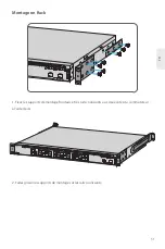
Page 32: ...1 4 3 6 5 8 7 10 9 12 11 14 13 16 15 18 17 20 19 22 21 24 23 1 2 3 26 100G 25 4 Breakout FR 31 Montage en Rack 1 Fixez les supports de montage frontaux et les rails coulissants aux deux côtés du commutateur à l aide de vis 2 Faites glisser les supports de montage sur les rails coulissants ...

Page 33: ...rre ne doit pas être retirée avant que toutes les connexions d alimentation n aient été déconnectées 1 Connectez une extrémité du câble de mise à la terre à une mise à la terre appropriée telle que le rack dans lequel le switch est installé 2 Fixez la cosse de mise à la terre au point de mise à la terre sur le panneau arrière du switch à l aide de rondelles et de vis ...

Page 34: ...itué sur le panneau arrière du switch 2 Connectez l autre extrémité du câble d alimentation à une source de courant alternatif Connexion au Port RJ45 1 Connectez un câble Ethernet au port RJ45 d une caméra IP téléphone IP point d accès ou d un autre périphérique réseau 2 Connectez l autre extrémité du câble Ethernet au port RJ45 du switch ATTENTION Ne pas installer les câbles d alimentation lorsqu...

Page 35: ...ibre optique au module puis connectez l autre extrémité du câble à un autre dispositif à fibre 3 Ou connectez directement le câble DAC AOC au port QSFP28 Connexion des Ports QSFP28 ATTENTION Les faisceaux laser peuvent causer des lésions oculaires Ne pas regarder directement dans les orifices des modules optiques ou des fibres optiques sans protection oculaire ...

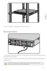
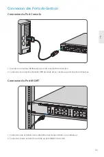
Page 36: ... ETH S5800 48M BQ 2 1 4 3 6 5 8 7 10 9 12 11 14 13 16 15 18 17 20 19 22 21 24 23 26 25 28 27 30 29 32 31 34 33 36 35 37 Connexion du Port MGMT 1 Connectez une extrémité d un câble Ethernet standard RJ45 à un ordinateur 2 Connectez l autre extrémité du câble au port MGMT du switch Connexion des Ports de Gestion SYS ID MGMT CON MGMT S5850 24XMG 2 1 4 3 6 5 8 7 10 9 12 11 14 13 16 15 18 17 20 19 22 2...

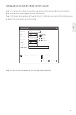
Page 37: ...8 1 1 et entrez le nom d utilisateur et le mot de passe par défaut admin admin Étape 4 Cliquez sur Sign in pour afficher la page de configuration basée sur le Web x OK Cancel General IP address Subnet mask Default gateway You can get IP settings assigned automatically if your network suppor ts this capability O ther wise you need to ask your network administrator for the appropriate IP settings In...

Page 38: ...finissez les paramètres de l HyperTerminal 115200 bits par seconde 8 bits de données pas de parité 1 bit d arrêt et pas de contrôle de flux Étape 4 Entrez le nom d utilisateur et le mot de passe admin admin x Quick Connect Protocol Serial Flow Control DTR DSR RTS CTS XON XOFF Save session Show quick connect on startup Open in a tab Connect Cancel COM3 115200 8 None 1 Port Baud rate Data bits Parit...

Page 39: ...er dans le mode Uboot 3 Démarrer le système avec un fichier de configuration vide sans mot de passe Bootrom boot_flash_nopass Bootrom Do you want to revert to the default config file Y N E 1 Vérifiez que l alimentation électrique est normale et que le câble de console est correctement connecté 2 Vérifiez si le câble de console est du bon type 3 Vérifiez si le pilote du câble de commande est correc...

Page 40: ...ctué dans les 30 Jours suivant la réception de la marchandise Ceci exclut les articles fabriqués sur mesure ou les solutions personnalisées Garantie Ce produit bénéficie d une garantie limitée de 5 ans contre tout défaut matériel ou de fabrication Pour plus de détails sur la garantie veuillez consulter la page https www fs com fr policies warranty html Retour Si vous souhaitez retourner un ou plus...

Page 41: ...If this equipment does cause harmful interference to radio or television reception which can be determined by turning the equipment off and on the user is encouraged to try to correct the interference by one or more of the following measures Reorient or relocate the receiving antenna Increase the separation between the equipment and receiver Connect the equipment into an outlet on a circuit differ...

Page 42: ...5 EU Eine Kopie der EU Konformitätserklärung finden Sie unter www fs com de company quality_control html FS COM GmbH hereby declares that this device is in compliance with the Directive 2014 30 EU and 2014 35 EU A copy of the EU Declaration of Conformity is available at www fs com company quality_control html FS COM LIMITED 24F Infore Center No 19 Haitian 2nd Rd Binhai Community Yuehai Street Nans...

Page 43: ...Copyright 2022 FS COM All Rights Reserved Q C PASSED ...

Reviews: