CA / CT SERIES
CAP600
Page
9 of 30
REV D July 2013
Installation Procedure
Step 1 – Select a proper location for installation
Select a clean, dry, well lit area with a rigid floor strong enough to support the compressor and
with adequate ventilation. Avoid placement of the compressor in an area that is excessively
hot, dusty, humid or contaminated with foreign gases such as ammonia or acid fumes.
The unit should never be operated at ambient temperatures above 104°F or below 32°F. If the
ambient temperature is below 40°F, FS Curtis recomm ends using Arctic oil. Maintenance
checks are required daily, thus three (3) feet of space needs to be provided around the
compressor for proper inspection.
Note – If the unit or air intake is to be located outdoors, please contact your local
distributor for additional instructions.
Step 2 – Remove the skid
Remove and discard the shipping skid. The compressor should NEVER be operated on a
skid.
Step 3 – Prepare the mounting surface
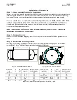
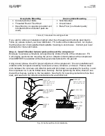
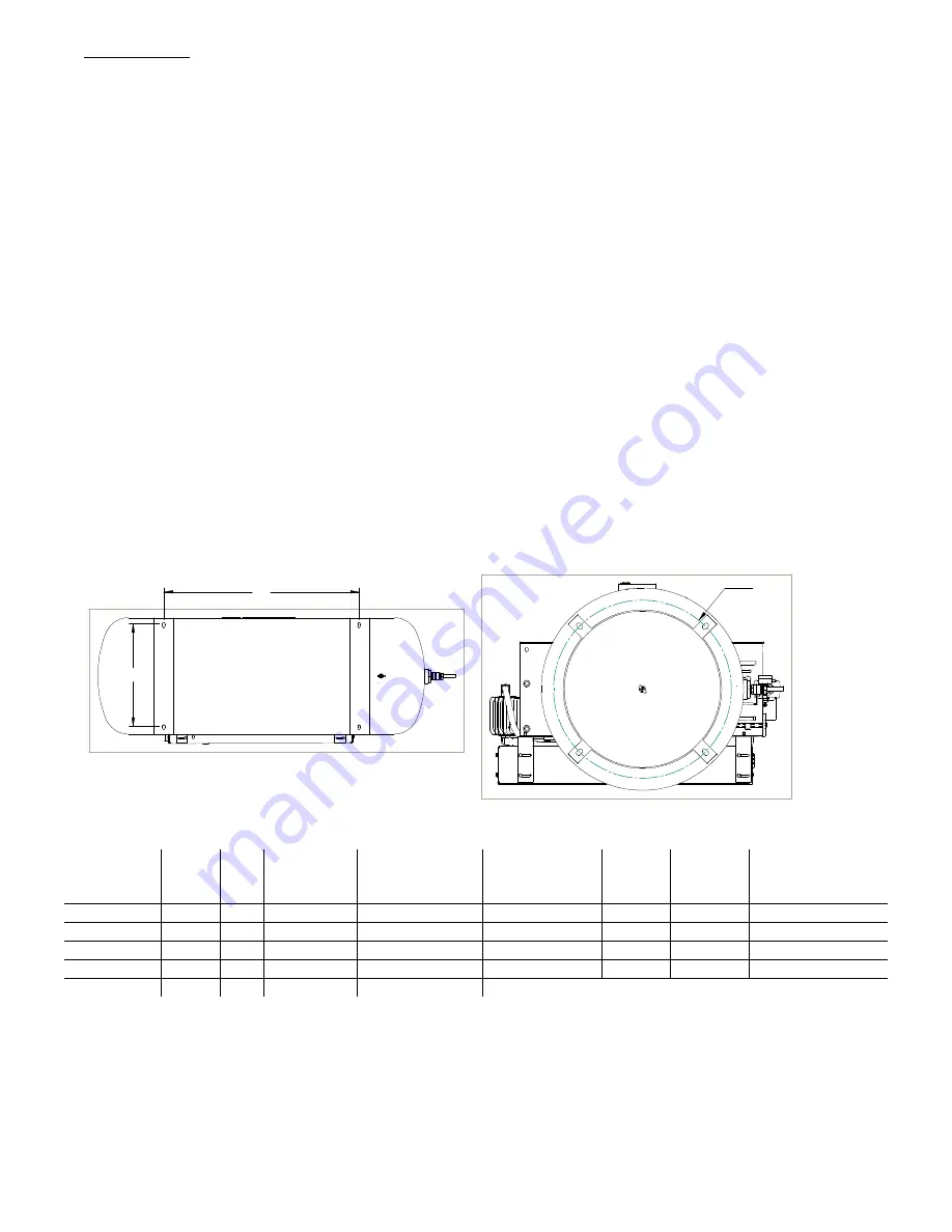
See Fig. (3) and Fig. (4) for the compressor’s mounting pattern and prepare the surface
accordingly. See Table (2) for acceptable installation methods
B
A
D
Fig. (3) Horizontal bolt hole pattern
Fig. (4) Vertical bolt hole pattern
Horizontal
Tank
(gallons)
A
(in)
B
(in)
Base Hole
Size (in)
Recommended
Bolt Diameter
(in)
Vertical Tank
(gallons)
D
(in)
Hole
Size (in)
Recommended
Bolt Diameter
(in)
30
17.75
23
9/16
1/2"
60
17
9/16
1/2”
80
17.75
40
9/16
1/2”
80 (CT line)
17
9/16
1/2"
120
22
40
9/16
1/2”
80 (CA Line)
22.5
11/16
5/8”
200
28
40
7/8
3/4”
120
26.375
11/16
5/8”
240
40
54
3/4
5/8”
Table (1) Bolt hole mounting patterns for various tank sizes.


