background image

TROUBLESHOOTING

OPERA

TION

ASSEMBL

Y

 /

 INST

ALLA

TION

SAFETY

 / 

SPECIFICA

TIONS

 GETTING 

ST

ARTED

14

MAINTENANCE /


REP

AIR

MAINTENANCE AND INSPECTION INSTRUCTIONS


Disconnect, tag and lock out power source then release all pressure 

  from the system before attempting to install, service, relocate or perform any 

maintenance.

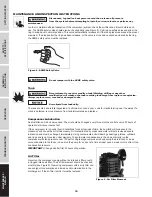
In order to maintain efficient operation of the compressor system, check the air filter and oil level before each 
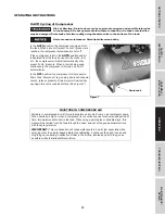
use. The ASME safety valve should also be checked daily (see Figure 8). Pull ring on safety valve and allow the 
ring to snap back to normal position. This valve automatically releases air if the tank pressure exceeds the preset 
maximum. If air leaks after the ring has been released, or the valve is stuck and cannot be actuated by the ring, 
the ASME safety valve must be replaced.

  Do not tamper with the ASME safety valve.

Tank


Never attempt to repair or modify a tank! Welding, drilling or any other 

  modification will weaken the tank resulting in damage from rupture or explosion. 

Always replace worn, cracked or damaged tanks.

  Drain liquid from tank daily.

The tank should be carefully inspected at a minimum of once a year. Look for cracks forming near the welds. If a 
crack is detected, remove pressure from tank immediately and replace.

Compressor Lubrication

See Installation. Add oil as required. The oil should be changed every three months or after every 200 hours of 
operation; whichever comes first.
If the compressor is run under humid conditions for short periods of time, the humidity will condense in the 
crankcase and cause the oil to look creamy. Oil contaminated by condensed water will not provide adequate 
lubrication and must be changed immediately. Using contaminated oil will damage bearings, pistons, cylinders 
and rings and is not covered under warranty. To avoid water condensation in the oil, periodically run the 
compressor with tank pressure near 120 psi for single stage compressors by opening the drain cock or an air 
valve connected to the tank or hose. Run the pump for an hour at a time at least once a week or more often if the 
condensation reoccurs.

IMPORTANT:

 Change oil after first 50 hours of operation.

Air Filter

Never run the compressor pump without an intake air filter or with 
a clogged intake air filter. The air filter element should be checked 
monthly (see Figure 9). Operating compressor with a dirty filter can 
cause high oil consumption and increase oil contamination in the 
discharge air. If the air filter is dirty it must be replaced.

Figure 8 - ASME Safety Valve

Figure 9 - Air Filter Element

Summary of Contents for FCT02C48H2X-A1X1XX

Page 1: ...EN 2015 Curtis Toledo Inc IN570600AV 12 15 Model FCT02C48H2X A1X1XX 20 Gallon Portable Air Compressor Operating Instructions and Parts Manual ...

Page 2: ...your dated proof of purchase for warranty purposes Attach it to this manual or file it for safekeeping Model _______________________ Serial ________________________ Purchase Date _________________ REGISTER YOUR PRODUCT ONLINE NOW http us fscurtis com support warranty register READ AND FOLLOW ALL INSTRUCTIONS SAVE THESE INSTRUCTIONS DO NOT DISCARD For parts product service information visit www fsc...

Page 3: ...resulting from such misuse QUICK REFERENCE Recommended Oil 2 Options FSC 1000A ISO 100 Premium Reciprocating Compressor Lubricant 1 quart part number FSC 1000A 1 12 quart case part number FSC 1000A 12 For generic option use 10W30 Oil Capacity Approximately 8 5 oz UNPACKING Do not lift or move unit without appropriately rated equipment Be sure the unit is securely attached to lifting device used Do...

Page 4: ...als known to the State of California to cause cancer and birth defects or other reproductive harm Wash hands after handling You can create dust when you cut sand drill or grind materials such as wood paint metal concrete cement or other masonry This dust often contains chemicals known to cause cancer birth defects or other reproductive harm Wear protective gear Important Safety Information Please ...

Page 5: ...lasses and use hearing protection when operating the unit Do not stand on or use the unit as a handhold Before each use inspect compressed air system and electrical components for signs of damage deterioration weakness or leakage Repair or replace defective items before using Check all fasteners at frequent intervals for proper tightness Motors electrical equipment and controls can cause electrica...

Page 6: ... may be harmful Release air slowly when draining moisture or depressurizing the compressor system Spraying Precautions Do not spray flammable materials in vicinity of open flame or near ignition sources including the compressor unit Do not smoke when spraying paint insecticides or other flammable substances Use a face mask respirator when spraying and spray in a well ventilated area to prevent hea...

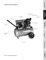
Page 7: ...MBLY INSTALLATION GETTING STARTED 5 SAFETY SPECIFICATIONS Figure 1 Horizontal Unit Identification Getting To Know Your Compressor Handle Beltguard Tank Pressure Gauge Motor Compressor Pump Discharge Tube Pressure Switch Air Filter Regulator Tank Drain ...

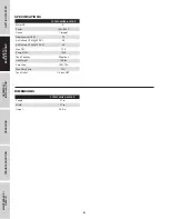
Page 8: ...NS FCT02C48H2X A1X1XX Motor HP 2 Power 120V 240V Phase 1 single Displacement CFM 7 2 Air Delivery CFM 90 PSI 5 5 Air Delivery CFM 135 PSI 4 9 Max PSI 135 Pump RPM 1020 Tank Capacity 20 gallons Unit Weight 148 lbs Amp Draw 15A 7 5A Max Duty Cycle 75 Tank Outlet 1 4 inch NPT FCT02C48H2X A1X1XX Length 37 in Width 21 in Height 30 5 in ...

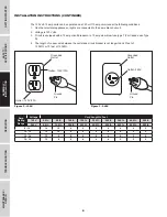
Page 9: ...Check motor data plate for 240 volt compatibility A 240 volt unit must be operated on a 240 volt circuit The cord must only plug into a 240 volt grounded outlet and may require a new cord and plug See Figure 3 Use only a 3 wire extension cord that has a 3 blade grounding plug and a 3 slot receptacle that accepts the plug on the product Make sure your extension cord is not damaged When using an ext...

Page 10: ...slow blow fuse type T For Canada use Type D 4 The length of copper wire between the outlet and circuit breaker is not longer than 40 feet of 14 AWG or 70 feet of 12 AWG Amp Rating Range Voltage Cord Length in Feet 120V 25 ft 50 ft 100 ft 150 ft 200 ft 250 ft 300 ft 400 ft 500 ft 240V 50 ft 100 ft 200 ft 300 ft 400 ft 500 ft 600 ft 800 ft 500 ft 8 10 14 10 8 6 6 6 4 4 2 10 12 12 10 8 6 6 4 4 2 2 12...

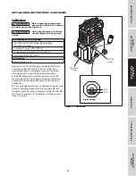
Page 11: ...Approximately 8 5 oz Remove cap from oil fill opening Install breather found in parts bag with this manual Check oil level See specification label on compressor pump for the proper oil capacity and oil type All lubricated compressor pumps discharge some condensed water and oil with the compressed air Install appropriate water oil removal equipment and controls as necessary for the intended applica...

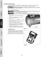
Page 12: ...tank 1 Check oil level per the Lubrication Section of this manual 2 Open the bottom tank drain valve see Figure 5 Turn outlet valve to open air flow 3 Plug unit in 4 Move pressure switch to the AUTO position to run the unit see Figure 6 5 Run the unit for thirty 30 minutes at zero 0 psi under no load to break in pump parts 6 Move the pressure switch lever or knob to OFF and turn tank drain valve t...

Page 13: ... being used continuously the compressor will cycle on and off automatically In the OFF position the compressor will not operate Drain Tank Disconnect tag unplug and lock out power source release pressure Drain moisture from tank by opening drain valve underneath tank See Figure 7 MOISTURE IN COMPRESSED AIR Moisture in compressed air will form into droplets as it comes from an air compressor pump W...

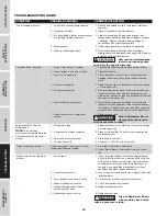
Page 14: ...pressor head and valve plate and inspect for carbon deposits or other foreign matter on top of piston Replace head and valve plate using new gasket See Lubrication section for recommended oil 7 Noisy check valve in compressor system 7 Replace check valve Risk of Explosion Do not disassemble check valve with air pressure in tank Large quantity of oil in the discharge air NOTE In an oil lubed compre...

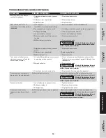
Page 15: ...r s 8 Replace capacitor s 9 Malfunctioning motor 9 Replace motor Tank does not hold pressure when compressor is off and the shut off valve is closed 1 Air leaks fittings tubing on compressor or plumbing outside system 1 Check all connections with soap and water solution Tighten or remove and apply sealant to threads then reassemble 2 Worn check valve 2 Replace check valve Risk of Explosion Do not ...

Page 16: ...e welds If a crack is detected remove pressure from tank immediately and replace Compressor Lubrication See Installation Add oil as required The oil should be changed every three months or after every 200 hours of operation whichever comes first If the compressor is run under humid conditions for short periods of time the humidity will condense in the crankcase and cause the oil to look creamy Oil...

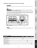
Page 17: ...he face of the flywheel and touching the rim on both sides of the face The belts should be parallel to this straight edge see Figure 10 Dimension A should be the same as B and C to ensure proper alignment of the belts Slots in the bed plate allow for sliding the motor back and forth to adjust belt tension Storage If compressor is to be stored for a short period of time make sure that it is stored ...

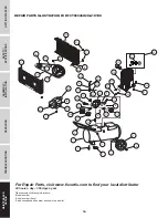
Page 18: ...ibutor 24 hours a day 365 days a year Please provide following information Model number Serial number if any Part description and number as shown in parts list REPAIR PARTS ILLUSTRATION FOR FCT02C48H2X A1X1XX 9 O T U A F F O 40 51 52 32 51 31 6 4 7 8 9 5 3 2 1 12 14 15 16 10 11 19 20 26 25 24 34 28 27 30 29 17 18 21 22 39 38 37 42 43 44 36 45 35 23 46 47 4 50 49 17 13 16 ...

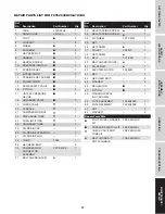
Page 19: ...FITTING 1 24 UNLOADER TUBE 1 25 OIL DRAIN CAP 1 26 OIL DRAIN EXTENSION 1 27 OIL DRAIN PLUG 1 28 PUMP FC48 1 29 HEX HEAD BOLT 4 30 COMPRESSION CONNECTOR ASSEMBLY FCT2 5CCA 1 31 BELT GUARD BACK 1 Ref No Description Part Number Qty 32 SELF TAPPING SCREW 3 33 SELF TAPPING SCREW 1 34 FLYWHEEL FCT2 5FW 1 35 KEY 1 36 SETSCREW 1 37 PULLEY FC48PY 1 38 SETSCREW 1 39 BELT FCT2 3B 1 40 BELT GUARD FRONT 1 41 P...

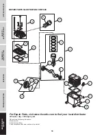
Page 20: ...provide following information Model number Serial number if any Part description and number as shown in parts list REPAIR PARTS ILLUSTRATION FOR FC48 MAINTENANCE REPAIR TROUBLESHOOTING OPERATION ASSEMBLY INSTALLATION SAFETY SPECIFICATIONS GETTING STARTED 18 6 4 9 3 1 10 13 7 12 15 11 16 14 2 5 8 17 18 19 20 8 ...

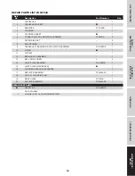
Page 21: ...SEMBLY FC48CRA 2 7 PISTON RING SET 2 8 BALL BEARING 2 9 CRANKSHAFT BEARINGS RODS PISTON ASSEMBLY FSK C48DK 1 10 O RING 1 11 OIL SEAL 1 12 BEARING CAP ASSEMBLY 1 13 M6 X 10 MM SCREW 4 14 VALVE PLATE ASSEMBLY FSK C48VK 1 15 VALVE PLATE MOLDED SEAL 1 16 CYLINDER HEAD AND FASTENERS 1 17 AIR FILTER ASSEMBLY FC48H2AFA 1 18 1 8 IN 27 OIL DRAIN PLUG 1 19 SIGHT GLASS FCT02SG 1 20 AIR FILTER ELEMENT FC48H2A...

Page 22: ...ned in accordance with FS CURTIS CURTIS TOLEDO INC s instructions as detailed in the operating manual provided with the compressor 4 Equipment that has been repaired or modified without authorization from FS CURTIS CURTIS TOLEDO INC D Pre delivery service i e assembly oil or lubricants and adjustment E The effects of normal wear and tear F Gasoline engines and components are expressly excluded fro...

Reviews: