background image

CAP-834 

MAY, 2018 

Rev. E 

WARNING 

Personal injury and/or equipment damage will be result by failing to pay attention to the vital safety information and instructions 

in this manual. Carefully read, understand, and retain all safety information and instructions before operating this compressor. 
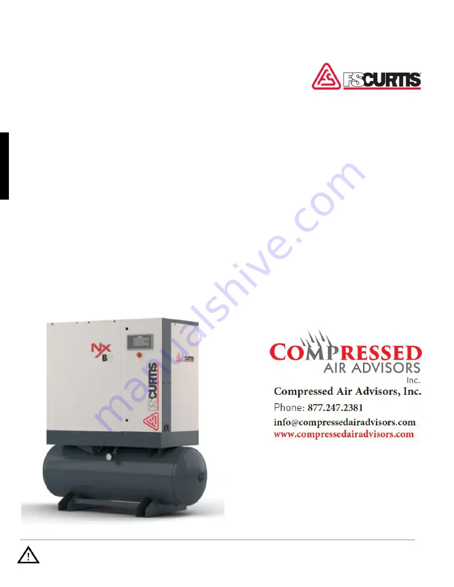
NxB/V

 Series 

OIL-INJECTED ROTARY SCREW COMPRESSORS

Operator Manual 

      4 

 15 kW 

Summary of Contents for NxB/V Series

Page 1: ...esult by failing to pay attention to the vital safety information and instructions in this manual Carefully read understand and retain all safety information and instructions before operating this compressor NxB V Series OIL INJECTED ROTARY SCREW COMPRESSORS Operator Manual 4 15 kW ...

Page 2: ......

Page 3: ... permission of the manu facturer Any infringement shall be subject to compensation for damages We reserve the right to assert further claims Limitation of liability All information and instructions in this manual have been compiled taking account of the applicable standards and regulations state of the art technol ogy and our years of knowledge and experience The manufacturer assumes no liability ...

Page 4: ... 13 1 4 Interfaces 13 2 Safety 14 2 1 Symbols in these instructions 14 2 2 Proper use 15 2 3 General safety 16 2 4 Safety devices 16 2 4 1 Position of the safety devices 16 2 4 2 Description of the installed safety devices 17 2 5 Environmental protection 17 2 6 Instructions on the machine 18 3 Technical data 20 3 1 Serial tag 20 3 2 General specifications 21 3 2 1 Operating conditions 21 3 2 2 Oil...

Page 5: ...y instructions for operation 31 6 2 Controller 31 7 Maintenance 32 7 1 Safety instructions for maintenance 32 7 2 Spare parts 34 7 3 Maintenance schedule 34 7 4 Maintenance work 36 7 4 1 Checking for leaks 37 7 4 2 Checking the electrical connections 37 7 4 3 Checking the oil level topping up the oil 37 7 4 4 Checking the build up of condensation 38 7 4 5 Checking the compressor temperature 39 7 4...

Page 6: ...Table of contents CAP 834 6 8 5 Commissioning after remedied fault 48 9 Index 49 10 Appendix 51 10 1 Bolt tightening torque requirements 51 ...

Page 7: ...y stop button 3 Electrical cabinet 4 Enclosure panels This chapter shows the screw compressors described in these instructions They mainly differ in their construc tion with or without receiver and with the attachment of an additional section in which the refrigeration dryer and the frequency converter are installed However their basic construction is the same ...

Page 8: ...d air receiver optional 1 Pressure gauge 2 Refrigeration dryer optional 3 Air receiver optional 4 Discharge port 5 Frequency converter optional 6 Air oil separator 7 Electrical cabinet 8 Safety valve second safety valve on tank for the option with compressed air tank positioned behind the pressure gauge 9 Compressor airend 10 Separator tank 11 Power connection 12 Drive unit 13 Minimum pressure and...

Page 9: ...or and flows to the oil cooler The oil temperature thermostat adds the cooled oil to the hot oil via the oil cooler bypass according to the set point temperature Fi nally the oil filter cleans the oil before it is injected into the compressor airend again 1 3 Assembly description 1 3 1 Controller Controller variants For detailed information about the controller installed consult the separate Contr...

Page 10: ...e fre quency converter Actuation is provided by a V belt 1 3 4 Intake filter Fig 6 Standard intake filter The standard intake filter Fig 6 1 is fitted directly on the compressor airend Fig 6 2 1 3 5 Compressor airend Fig 7 Compressor airend The air is compressed by the compressor airend Fig 7 1 and fed to the oil separator tank Fig 7 2 together with the injected oil The compressor airend and the o...

Page 11: ... The oil is topped up via the filler nozzle Fig 8 3 and removed via the oil drain Fig 8 4 1 3 7 Air oil separator Fig 10 Air oil separator The air oil separator Fig 10 1 removes the residu al oil from the compressed air 1 3 8 Minimum pressure and non return valve Fig 11 Minimum pressure and non return valve The minimum pressure and non return valve Fig 11 1 does not open until the system pressure ...

Page 12: ...with air receiver optional refrigeration dryer optional and or frequency converter 3 15 kWn The cooling of the air after cooler and of the oil cooler is performed by the cooling air fan The cool ing air fan also supplies the intake filter Fig 14 1 with sufficient intake air The cooling air inlet and outlet openings must be kept clear The required cooling air rates must be provided in accordance wi...

Page 13: ...ate drain otherwise the user will need to attach one 1 4 Interfaces Air supply Fig 16 Screw compressor with frequency converter air receiver optional and refrigeration dryer optional 3 15 kW The cooling air fan in the compressor housing di rects the fresh air to the intake filter and is also used for process cooling The intake filter filters the fresh air and directs it into the compressor unit fo...

Page 14: ...tent of the risk DANGER This combination of symbol and signal word indicates a directly hazardous situation which will lead to serious or even fatal injuries if not avoided WARNING This combination of symbol and signal word indicates a possibly hazardous situation which may lead serious or even fatal injuries if not avoided CAUTION This combination of symbol and signal word indicates a possibly ha...

Page 15: ...xclusively to gener ate compressed air in an environment not subject to explosion The screw compressor must be supplied exclusively with cool dry and dust free cooling air Do not operate the compressor in excess of its rated pressures and speeds indicated on the compressor nameplate The proper use also includes adherence to all de tails in this manual Any use beyond the proper use or other type of...

Page 16: ...xercise cleanliness during maintenance and when making repairs Keep dirt away from parts and exposed openings by covering with clean cloth or Kraft paper 12 Do not install a shut off valve in the discharge line without installing a pressure relief valve between the shut off and the compressor package 13 Do not operate the compressor in areas where there is a possibility of flammable or toxic subst...

Page 17: ...ge the pressure setting of the pres sure relief valve restrict the function of the re lief valve or replace the relief valve with a plug 2 5 Environmental protection NOTICE Danger to the environment from incorrect handling of pollutants Incorrect handling of pollutants particularly incorrect waste disposal may cause serious damage to the environment Always observe the instructions below regarding ...

Page 18: ... operating instructions cannot be complied with This in turn poses a risk of injury All safety warning and operating instructions must always be maintained in a completely legible condition Damaged signs or stickers must be replaced immediately Direction of rotation There is a direction of rotation sticker on the drive unit and on the cooling air ventilator This sticker shows the appropriate direc...

Page 19: ...Safety CAP 834 19 Brief instructions for operation This sticker is on the enclosure and contains brief instructions for operation ...

Page 20: ...tion refer to the technical data sheet 3 1 Serial tag Fig 20 Serial tag The serial tag can be found on the enclosure It includes the following details 1 Manufacturer 2 Part number 3 Serial number 4 Motor power HP 5 Discharge pressure PSI 6 Voltage V 1 2 3 4 5 6 ...

Page 21: ...e been tested and approved for use in these compressors Designation Type Synthetic oil FSC 8000 Food grade oil FSC 4000FG 3 2 3 Consumables Screw compressor with V belt drive with and without frequency converter type 3 7 Type Consumable Fill level 3 Oil 1 05 USG 4 Oil 1 05 USG 5 Oil 1 05 USG 7 Oil 1 05 USG Screw compressor with V belt drive with and without frequency converter type 8 15 Type Consu...

Page 22: ... shipper s delivery note Initiate complaint procedures Issue a complaint in respect of each defect immediately following detection Damage compensation claims can only be asserted within the applicable complaint deadlines 4 3 Packaging About the packaging The individual screw compressors are packaged in cartons or sometimes on wooden frames and ac cording to the anticipated transport conditions Onl...

Page 23: ...th the forks as shown in Fig 21 2 Insert the forks so that they stick out on the oth er side 3 Ensure that the package cannot tip if the centre of gravity if off centre 4 Lift the package and begin transportation 4 6 Storage Storage of the packaged compressor Store the compressor under the following condi tions Do not store outdoors Store dry and dust free Do not expose to any aggressive media Pro...

Page 24: ...horized restart In the event of an unauthorized restart of the power supply during installation there is a danger of serious injuries or death for persons in the danger zone Switch off all power supplies before starting work and make sure they cannot be switched on again Follow lockout tagout procedure Improper installation and commissioning WARNING Risk of injury due to improper installation or c...

Page 25: ...ic disturbance 5 3 Installation 5 3 1 Remove shipping spacers To protect the vibration isolators underneath the motor airend assembly during transport there are red spacers that hold the assembly in place Make sure all of these spacers are removed before first startup of the compressor Failure to remove the spacers will result in excessive vibration and can cause damage to the compressor Fig 22 1 ...

Page 26: ...ioned so that the required supply and exhaust air can be supplied and extracted taking into account the existing residual thrust from the cooling air fan The exhaust air can also be used for heat reclamation Fig 23 Overview illustration of air duct connection 1 For the nominal diameters of the duct connec tions and details about residual thrust refer to the technical data Chapter 3 Technical data ...

Page 27: ...pply Personnel Qualified Electrician NOTICE Property damage to the compressor airend due to incorrect connection of the power supply In case of incorrect connection of the power supply there is a danger that the compressor airend will be destroyed due to the drive turning incorrectly Connect the power according to the wiring diagram and check the rotating field before starting the screw compressor...

Page 28: ...end after longer downtimes e g between factory delivery and initial commissioning or after a longer downtime can cause significant material damage to the screw compressor Add 0 5 quarts of oil directly in the compressor airend before initial commissioning or after a longer downtime Fig 26 Intake valve fastening screw 1 Unfasten the fastening screws on the intake valve Fig 26 1 NOTICE Property dama...

Page 29: ...stant protective clothing and protective gloves during all work near hot surfaces Before all work make sure that all surfaces have cooled off to the ambient temperature wait at least 30 minutes CAUTION Danger of injury from oil vapor In case of high temperatures oil vapor can form Oil vapor can irritate eyes and the respiratory system When working on the oil system and if an oil vapor arises wear ...

Page 30: ... the compression temperature is sufficiently high this ensures that the air humidity taken in does not form condensation Frequent switching on and off of the screw compressor can prevent the compressor from reaching the required operating temperature Chapter 7 4 4 Checking the build up of condensation on page 38 9 Check the compressor temperature Chapter 7 4 5 Checking the compressor temperature o...

Page 31: ...g steps in accordance with the information and notices in this manual Pay attention to the following points before starting work Ensure that all covers and safety devices are installed and work properly Ensure that that no one is in the danger zone Never override or bridge safety features during operation 6 2 Controller Controller documentation Refer to the controller documentation for information...

Page 32: ...of an unauthorized restart of the power supply during maintenance there is a danger of serious injuries or death for persons in the danger zone Switch off all power supplies before starting work and make sure they cannot be switched on again Use a lock out and tag out process Hot surfaces WARNING Danger of injury from hot surfaces Surfaces of components can heat up a lot during operation Skin cont...

Page 33: ...led movements of hoses Components under pressure can move in uncontrolled fashion with improper handling and cause injuries Before removing hoses or components under pressure make sure the pressure is relieved Have faulty components that are under pressure during operation replaced by appropriate specialist personnel immediately Before all work make sure that the compressor is not under pressure w...

Page 34: ...se damages malfunctions or complete failure Only use genuine spare parts supplied by the manufacturer or manufacturer approved spare parts If in doubt always contact the manufacturer Loss of warranty The use of non approved spare replacement parts will invalidate the warranty Procure replacement parts from authorized dealers or directly from the manufacturer Please refer to the Parts list for accu...

Page 35: ...trols Check oil scavenger line for oil flow Drain condensate from air receiver Check pressure relief valve for operation3 Drain condensate from sump Inspect clean air suction filter element Inspect clean panel filters Inspect clean finned surface of cooler s Check for loose fittings and fasteners Inspect hoses for signs of wear4 Change oil filter 1 Oil sample VO701 POL 1 Motor bearing lubrica tion...

Page 36: ... result may cause severe injury or death 3 Replace as necessary or every 5 years 4 Visual check weekly Re tension and re align 50 hours after belt change Check tension and alignment every 500 hours thereafter Change belts every 4 000 hours or as needed Refer to the FS Curtis Technical Bulletin W 20151213 TB003 for detailed instructions on belt replace ment tensioning and pulley alignment The maint...

Page 37: ... even after the system has been switched off and disconnected from the power supply Contact with these components may result in serious or fatal injury Before working on the specified components ensure that they have been completely disconnected from the power supply Allow 10 minutes to elapse in order to ensure that the internal capacitors have been fully discharged 1 Close the shut off valve on ...

Page 38: ...erature systems use only fully synthetic oil FSC 8000 Fig 30 Filler pluge 5 Use a funnel Fig 30 1 to top up the oil to the filling edge on the filler plug Fig 30 3 6 Position the gasket and check that it is firmly in place 7 Insert the screw plug Fig 30 2 and tighten 7 4 4 Checking the build up of condensation If the compression temperature is sufficiently high this ensures that the air humidity t...

Page 39: ...er 7 4 3 Checking the oil level topping up the oil on page 37 7 4 5 Checking the compressor temperature NOTICE Property damage due to compressor temperature that is too low or too high A compressor temperature that is too low or too high can cause damage to the screw compressor For detailed information contact the manufacturer The compressor temperature should be between 158 and 212F 70 C and 100 ...

Page 40: ...nclosure doors with the special wrench 3 Use a drip pan to make sure that the leaking oil is collected Fig 32 Filler nozzle 4 Unfasten the filler nozzle Fig 32 1 remove it and make sure that the gasket is not misplaced Fig 33 Oil drain 5 Open the oil drain Fig 33 2 The oil is drained 6 Close the oil drain Fig 33 2 NOTICE Property damage due to incorrect oil Mixing different oils or using incorrect...

Page 41: ...6 1 The oil is drained 6 Close the oil drain Fig 36 1 Fig 37 Removing the oil filter 7 Use the strap wrench to unfasten and remove the old oil filter Fig 37 1 8 Remove old gasket remains from the oil filter housing 9 Moisten the new gasket with a little oil 10 Screw in the new oil filter Fig 37 1 all the way 11 Tighten the new oil filter Fig 37 1 half a turn by hand 12 Switch on the compressor and...

Page 42: ...e new air oil separator Fig 39 1 half a turn by hand 7 4 10 Replacing the intake filter Standard intake filter 1 Close the shut off valve on the pressure network side and secure it to prevent it from being opened again 2 Open and remove the enclosure panels with the special wrench Fig 40 Unfastening the clamp on the intake filter 3 Unscrew and remove the cover from the intake filter Fig 40 1 4 Rem...

Page 43: ... replaced properly 2 Ensure that all tools materials and other equip ment used have been removed from the work area 3 Carefully open the compressed air network side shut off valve 4 Clean the work area and remove any substanc es such as liquids processing material or similar that may have escaped 5 Ensure that all safety equipment on the machine functions perfectly 6 Document work on the machine i...

Page 44: ...r zone Switch off all power supplies before starting work and make sure they cannot be switched on again Improperly executed troubleshooting work WARNING Danger of injury from improper troubleshooting Improperly executed troubleshooting work may result in serious injury and significant damage to property Ensure sufficient assembly space before starting work Pay attention to orderliness and cleanli...

Page 45: ...e compressor is not under pressure wait at least 5 minutes Oil vapor CAUTION Danger of injury from oil vapor In case of high temperatures oil vapor can form Oil vapor can irritate eyes and the respiratory system When working on the oil system and if an oil vapor arises wear breathing protection and protective goggles and ensure that there is a fresh air supply Behavior in the event of faults The f...

Page 46: ...ged Replace intake filter Chapter 7 4 10 Replacing the intake filter on page 42 Bleeder valve blows during compression Check bleeder valve and replace gaskets if necessary Intake valve does not open Check magnet valve and plunger and replace if neces sary Leaks in the compressed air network Seal up the compressed air network Screw compressor blows via safety valve Minimum pressure valve blocked Cl...

Page 47: ...re Heed network pressure and change settings Controller documentation Symbol remote flashes Remote control activated Controller documentation Lacking voltage on the screw compressor Check whether there is voltage Electrical fault in the control ler Check controller Switching times are activated in the circuitry Check switching and pressure times in the circuitry Controller documentation Compressed...

Page 48: ...g 41 Return line 5 Unfasten the return line Fig 41 1 on the air oil separator Fig 41 2 and the compressor airend Fig 41 3 6 Clean the return line Fig 41 1 and nozzle If necessary replace them with original spare parts Parts List 7 Place the nozzle and return line Fig 41 1 back in position and tighten the screw connections 8 5 Commissioning after remedied fault After remedying the fault carry out t...

Page 49: ...ower supply 27 Consumables 21 Coolant liquid 21 Coolant liquid filter 12 Cooler 12 Cooling air fan 12 Copyright 3 Customer service 3 D Description of function 9 Drive unit 9 Dryer 13 E Emergency stop button 17 Environmental protection Coolant liquid 17 Lubricants 17 Explanation of symbols 14 F Fault displays 45 Fault table 46 Filler nozzle 11 Forced ventilation and bleeding system 26 I Inspection ...

Page 50: ...r replacing 40 Oil level 37 Oil separator tank 11 Operating conditions 21 Overview of the components 8 of the screw compressor 7 P Packaging 22 Proper use 15 R Relief valve 11 Relief valves 17 Replacing the intake filter 42 S Safety 14 Safety devices 16 Serial tag 20 Shipping spacers 25 Sight glass 11 Spare parts 34 Storage 23 Symbols on the machine 18 on the packaging 22 T Technical data Consumab...

Page 51: ... lbf ft Nm Lock screw nuts DIN 912 931 933 934 982 design or similar Thread Category 8 8 Unit Category 10 9 Unit M 5 4 43 6 lbf ft Nm 6 27 8 5 lbf ft Nm M 6 7 38 10 lbf ft Nm 10 33 14 lbf ft Nm M 8 18 44 25 lbf ft Nm 25 81 35 lbf ft Nm M 10 36 14 49 lbf ft Nm 50 89 69 lbf ft Nm M 12 63 43 86 lbf ft Nm 88 51 120 lbf ft Nm M 16 154 89 210 lbf ft Nm 217 58 295 lbf ft Nm 10 2 Oil change intervals at e...

Page 52: ......

Reviews: