CAP881
- 10 -
C. Precaution for piping foundation and cooling system
1. Air piping
(1). Install required accessories.
(2). Main piping should have 1˚- 2˚ slope away from compressor to drain the condensate.
(3). Pressure drop of piping must not exceed 5% of discharge pressure. Select larger piping
than required for better efficiency.
(4). Branch line must be located at the top side of main piping to avoid the condensate from
flowing to the equipment.
(5). To prolong service life of pneumatic tools, install an air filter regulator unit on the
outlet.
(6). Do not randomly reduce the size of the main piping. Use the proper reducer if
necessary to reduce pressure losses.
(7). The ideal installation arrangement of air solution is air comp air tank + dryer.
The air tank is capable of draining some of the condensate and cooling down the
temperature of compressed air. This will lead to more efficient dryer operation.
(8). If the air requirement is large in a short period of time, install a higher volume air tank
to reduce the frequency of full/off load control.
(9). The ideal main piping is constructed around the factory as a loop which is better for
delivering compressed air from both sides at any point.
2. Foundation
(1). Select a solid and level surface to install the compressor.
(2). There is no need to construct a base for the screw air compressor since the vibration is
relatively small. However, the area must be flat and strong enough to support the
weight of the unit.
3. Cooling system
Install an air-cooled compressor in a well-ventilated area to avoid high temperature
shutdown. If placed in a sealed room, air extracting and removal apparatus is required
and its capacity must be larger than the cooling fan in the compressor.
Summary of Contents for SEG-10
Page 11: ...CAP881 11 ...
Page 12: ...CAP881 12 ...
Page 13: ...CAP881 ...
Page 14: ...CAP881 14 ...
Page 15: ...CAP881 ...
Page 16: ...CAP881 16 ...
Page 17: ...CAP881 17 ...
Page 18: ...CAP881 18 ...
Page 20: ...CAP881 20 ...
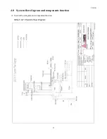
Page 24: ...CAP881 24 SEG 10 15 System Flow Diagram ...
Page 32: ...CAP881 32 6 0 Maintenance 6 1 Maintenance Intervals ...
Page 44: ...CAP881 44 NOTES ...


