FSM AG
| Erich-Rieder-Straße 2 | D-79199 Kirchzarten | vertrieb@fsm.ag | www.fsm.ag
13.09.2018
3 | 4
Application Description
Application-Description of the coil inter-connection at 3 phase transformers for a particular vector group. For the correct
function of the Transformer Switching Relay TSRD, to switch on 3 phase transformes without inrush current peaks, the
transformer coil endings must be connected in the right manner to the TSRD and must also be inter-connected in the right
manner for the particular vector group.
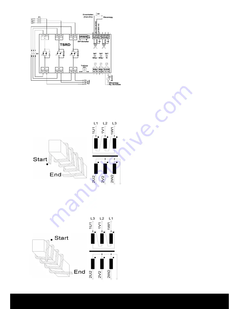
What means the begin of the coil,
marked with a dot, and the definition
of the direction of the bring up for
the windings
Usual manner of the inter connection from the coils
for a Delta Star vector group and the connections
from the transformer clamps L1, L2, L3 to the clamps
L1, L2, L3, from the TSRD, when windings are put on
in a clockwise manner onto the Iron core, if looking to
the top of the coil and to the winding start, for a DYN5
vector group transformer.
The dot marks the begin, start, of the windings on the
view from top for the bringing up of the windings.
Sometime it happens, that the coils are produced in a count clock wise winding direction onto the core, like showed in
the bottom left. The numbering of the clamps of the transformer must than be changed like showed in the picture in the
bottom right, L3 left and L1 right and similar connected L3 to L3 and L1 to L1 of the TSRD, for softstart the transformer
without inrush current peaks, via the TSRD and only with the value of the no load current at a delta vector group of the
primary side. (The interconnection of the coils for the Delta vector group is then corresponding to the connections showed
in the picture on the top rigt, L1 left and L3 right.)
View to top of the iron core, if the
coils are produced in a count clockwi-
se manner.
View to top of the iron core, if the coils are produced
in a count clockwise manner.
Thats not usual but it can happen. Connections for the
Delta vector group in the usual manner, however with
exchanged connections L1 and L3, if the windings are
bring up count clock wise..
Disclaimer:
Improper installation and commissioning can result in property
damage and endanger people in a row. FSM AG accepts no res-
ponsibility or liability for loss, damage or expense resulting from
improper installation, commissioning improper operation, and
improper use and maintenance.
Fuse with F1:
The need in the data sheet (Page 3) under
„Current“ defined limits are met. If this is not
possible, the TSRD should according to the circuit
example (see last page) are connected.
Terminal connection diagram


