background image


18

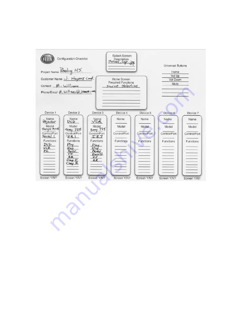
Below is an example of our checklist, which illustrates the devices we’re going to 

control, and the functions of each device. This is a useful tool in evaluating what 
screens the project requires. 


STEP


FOUR:


Templates


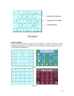
The FLEX Configuration Utility is a template‐based system where buttons and labels 
are placed on our screens in predetermined locations. Below is an example of one of 

the templates. The templates have three different size placeholder the large 
placeholder is to design to accommodate the large buttons. The middle‐sized 

buttons accommodate the smaller buttons. The small placeholders are for the 

placement of text labels. 

Summary of Contents for FLEX LT-100

Page 1: ...32606 LIT1369 FLEX Training Manual System Design FSR 244 Bergen Blvd Woodland Park NJ 07424 ...

Page 2: ...2 ...

Page 3: ...10 Analog Input 11 Designing a System 12 Hardware considerations 12 Display 12 Switchers 13 Audio control 13 Screen Control 13 Distance Limitations 13 IR Considerations 13 Serial Considerations 13 Ethernet Considerations 14 Designing a System Using FLEX 14 Designing the system 15 STEP ONE Devices to Control 15 STEP TWO Functions to Control 16 STEP THREE Screens 17 STEP FOUR Templates 18 Sample Tem...

Page 4: ...utility features an easy to use method to get the most out of the system The contractor is presented with an easy to follow drag and drop programming methodology There is no need to learn another programming language FLEX Hardware There are four models of the FLEX the LT 200 LT 300 LT 150 and the LT 100 Let s look at the differences between the four products The FLEX LT 200 hardware features 3 5 C...

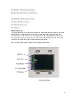
Page 5: ...e FLEX front panel by removing the plastic bezel The front panel has two communication ports RS 232 and mini USB for future use The communication port is used to load configurations into the FLEX panel Below the communication ports is the hardware reset switch The FLEX panel also has an IR receiver for future use See the panel illustration below NOTE The USB port and IR Receiver are currently inop...

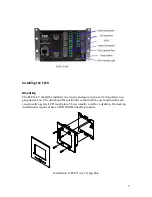
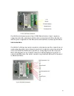
Page 6: ...tors for both communication and power The Ethernet port uses a standard RJ 45 connection All other connections use a plug able screw terminal style connector for device wiring The images below illustrate the connection panels from the LT 100 LT 200 and LT 300 FLEX systems ...

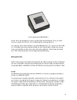
Page 7: ...as a Carlon plastic two gang device box The unit should be positioned so that both the user and installer can conveniently operate LCD touch plate This is usually a wall or a desktop If a desktop installation is required use an FSR DSKB 2 desktop console Installation of FLEX in a 2 Gang Box ...

Page 8: ...ing for the FLEX LT 200 and the LT 300 are identical The LT 300 does not have a separate serial port for loading projects Connect cable provided in FLEX Programming Kit to SERIAL 2 as illustrated below to load projects to a FLEX LT 300 Power The FLEX control panel is powered with either a 12V power supply included or power over Ethernet PoE To use the power supply strip both conductors back in and...

Page 9: ...ns Serial connections The FLEX LT 200 has four serial connectors on the back panel The connections are made using plug able screw terminal connectors To make the connection strip the wires as needed The FLEX control panel has a wiring diagram on the rear panel Wire each pluggable screw terminal connector as illustrated below Each pair of serial connections share the center connector as ground with...

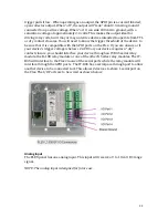
Page 10: ...d General Purpose I O The Flex has 4 GPIO ports It is important to note that these are different from dry contact closures and do not have the same functionality The GPIO ports can be configured as Inputs or Outputs As an Input a voltage of 2 4 VDC to 24 VDC will read as a 1 while a voltage below 1 0 VDC will read as a 0 When interfaced to TTL or CMOS logic the Flex inputs are directly compatible ...

Page 11: ...ts on the Flex If you are unsure or if your device s trigger voltage is below 2 4VDC or your device requires a dry contact closure you should interface your device through an IT R4S serial relay module the K 10D relay module or one of the other K Series relay modules The IT R4S will interface to the Flex via one of the serial ports while the relay module will interface through the GPIO ports The I...

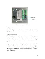
Page 12: ...me control be handled These questions will all need to be considered when looking at the hardware used in the system Let s look at some of the considerations for each type of hardware Display The primary thing to look at when selecting the display is how will it be controlled The typical display has either IR or serial control There are several advantages to having serial control Devices using ser...

Page 13: ...V system there are many methods to choose from Many manufacturers provide the option of either serial IR or contact closure control for the screen If you elect to use contact closure check the specifications from the manufacture You may require an external serial to relay converter such as the FSR Intelli tools ITR4S to control your screen Check the voltage requirements from the screen manufacture...

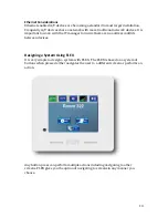
Page 14: ...anager to insure there are no address conflicts between devices Designing a System Using FLEX It is very simple to design a system with FLEX The FLEX is based on a system of buttons when pressed either navigates the user to a different screen or performs an action Any button press can perform multiple actions including navigating to other screens FLEX gives you the option of navigating to screens ...

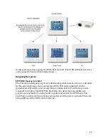
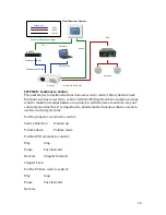
Page 15: ...to be controlled In the system below we have a projector a DVD VCR and a computer On the projector we will switch sources and control volume levels We will also provide transport controls for the DVD VCR Next step is to determine any additional screens we may desire You may want a separate screen for the DVD menu You could have a wait screen to indicate your system is in the power up mode These ar...

Page 16: ... functions we may not want to control with the FLEX system For example you may want to make focus adjustments on a projector with the remote and not use your control system for this It is important to determine the functions that we want to use the control system for For the projector we want to control Source Selection Volume up Volume down Volume mute For the DVD we want to control Play Stop Pau...

Page 17: ...e want in our control system In a typical system we want a screen for every group of functions we are going to control For example we will have a screen for input selection We may not have a screen for every device For example if we re using a switcher for source selection we may not have a screen for our display We also need to determine if we need additional screens for a device For example you ...

Page 18: ... The FLEX Configuration Utility is a template based system where buttons and labels are placed on our screens in predetermined locations Below is an example of one of the templates The templates have three different size placeholder the large placeholder is to design to accommodate the large buttons The middle sized buttons accommodate the smaller buttons The small placeholders are for the placeme...

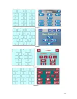
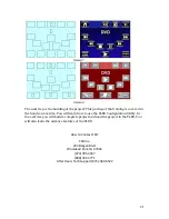
Page 19: ...e Templates The Configuration Utility has eight different templates available for different system configurations Below is an illustration of each template and an example of a screen created using that template ...

Page 20: ...20 ...

Page 21: ...will learn how to use the FLEX Configuration Utility In the exercise you will build a complete project and load the project in the FLEX You will also learn the advance features of the FLEX How to Contact FSR FSR Inc 244 Bergen Blvd Woodland Park NJ 07424 973 785 4347 800 332 3771 After Hours Tech Support 973 580 0522 ...

Reviews: