background image

Quick installation Guide ATLAS 64 

We reserve the right to make technical changes without prior notice

The manufacturer accepts no liability arising from printing errors. 


- 4 - 


ATLAS 64 Version en_1.1 (Fte maximal) 


4.


Installation 

When the device is installed in a wall, keep clean and without obstacles a minimum radius of 15 
cm  around  this  equipment  for  proper  ventilation.  Connect  the  cables,  from  the  LNB  or 
multiswitch to the input RF IN 1 to RF IN 4. The output signals in the RF output can be mixing 
with  the  output  terrestrial  signals  of  other  headend  equipments  using  the  MIX  RF  connector 
before to distribute in the building. If the MIX RF input is not used connect the load 75 

Ω isolated 

included. To programming the headend, connect a patch cord between the LAN connector and 
the computer or connect the both device using a switch or router.  
 
Always  remember  to  turn  off  the  ATLAS  64  headend  before  to  install  or  remove  the  CAM  to 
avoid  damage  in  the  headend  or  the  CAM. Before  to  install,  check  the  side  of  the  logo of  the 
CAM must be orientating to the back side of the headend. 

5.


Configuring the compact headend ATLAS 64 

5.1.


First steps 

After finish the installation of the headend Atlas 64 is ready to connect the power. Wait until the 
led  alarm  is  off  again.  This  time  could  be  more  than  three  minutes.  To  configure  the 
transmodulator is necessary a computer or a mobile device with a web browser. For example: 
Google Chrome, Firefox, Opera and Internet Explorer 9. In this guide is explaining the steps to 
configure  the  Atlas  64  from  one  computer  with  Windows  operative  system  using  the  network 
interface Ethernet.  
 
Connect the LAN port of the transmodulator and the interface Ethernet of the computer directly 
using a patch cord or use a switch or router between the both devices connecting with 2 patch 
cords. By default, the Atlas 64 is configured to obtain the IP address by DHCP. 
 

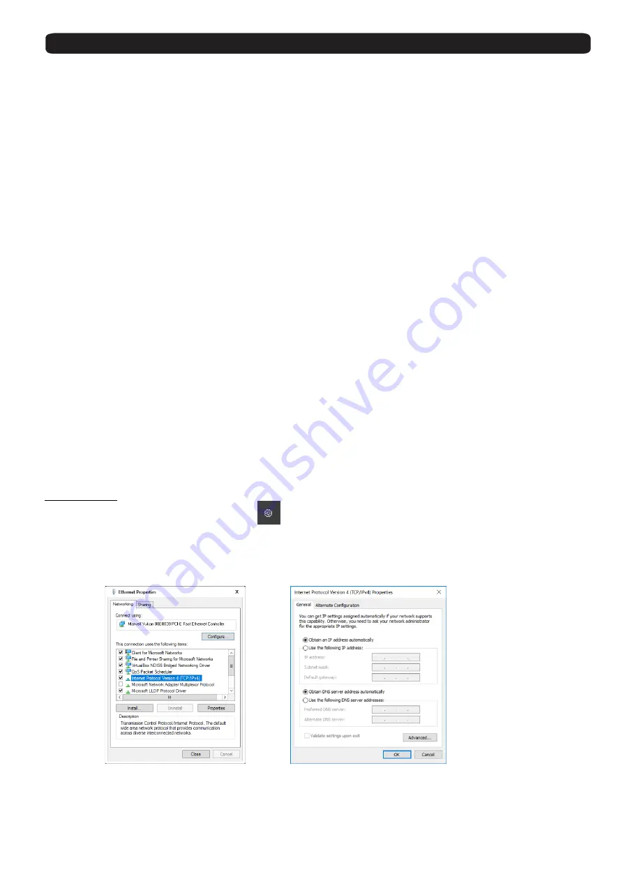
Windows 10 

Click  in  the  Windows  start  button 


  Settings    

 Network  and  Internet   

 Ethernet   


Change Adapter Settings. Right 

click on “Local Area Connection” and then select “Properties” in 

the contextual menu.  
Follow  the  next  steps  to  set  the  properties  of  the  Internet  protocol  Version  4.  Double  click  on 
“Internet Protocol Version 4 (TCP/IPv4)” to enter the IP settings of your adaptor. 


Configuring the protocol TCP/IPV4 to Obtain an IP address from DHCP


In  the  computer  Select  obtain  an  IP  address  automatically  and  Obtain  DNS  server  address 
automatically.  

Summary of Contents for ATLAS 64

Page 1: ...ATLAS 64 QUICK INSTALLATION GUIDE...

Page 2: ...ATLAS 64 ENGLISH QUICK INSTALLATION GUIDE...

Page 3: ...quipment to dripping or splashing 4 Do not place objects filled with liquids on the equipment 5 Respect ventilation slots of this equipment Avoid covering them with any object 6 Keep clean and without...

Page 4: ...f the 4 available RF inputs Atlas 64 is able to decode pay per view services when a professional CAM is inserted in any of the 2 slots C I Each output mux can combine free or decoded services coming f...

Page 5: ...paper If hold the button reset 2 seconds the headend will be rebooting and the led ALARM will be turn on in red color If hold the button more than 5 seconds the headend load the factory values All the...

Page 6: ...d ATLAS 64 5 1 First steps After finish the installation of the headend Atlas 64 is ready to connect the power Wait until the led alarm is off again This time could be more than three minutes To confi...

Page 7: ...in the IP address 192 168 5 77 Remember copy the current configuration before to do any change if need restore the current configuration of the Ethernet interface Check the radio button Use the follo...

Page 8: ...om printing errors 6 ATLAS 64 Version en_1 1 Fte maximal 6 1 Men Device 6 1 1 Overview Show the information of the output mux and CAM 6 1 2 Information Show information about the software and hardware...

Page 9: ...e the password Type the current and the new password and press Apply to update the change The current session will be close and you must be login with the new password to continue Dynamic DNS This opt...

Page 10: ...Export to save the current devices settings in a file 6 1 8 Reset Device In this option it is possible choose the type of reset In the list Select reset level choose an option and press the button App...

Page 11: ...Enable If the option is checked the input is enabled Press the button Apply to update the change in the device 6 2 2 Tuner This section allows change the settings of the 6 tuners of the headend and sh...

Page 12: ...pending of the output modulation it is possible choose one option in the list DVB T QPSK 16 QAM and 64 QAM DVB C 16 QAM 32 QAM 64 QAM 128 QAM and 256 QAM Baud Rate MBd 1 Option only for DVB C Choose t...

Page 13: ...this option is possible change the service ID If leave in blank keep the original service ID after was added LCN Type here the logical channel number to sort the channels in the compatible receivers...

Page 14: ...of the network Version Type the value of the network version The allowed values are between 1 and 31 Private data Specifier Select between the next values EACEM ITC and Nordig Press Apply to confirm...

Page 15: ...check the enable option and selects the correct reference tuner to decrypt services by the CAM The reference tuner must be one tuner where is received services any Pay TV compatible with the CAM Sele...

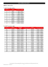
Page 16: ...service to any output mux CI Slot 2 RF Output Number of connectors 1 Number of output mux 4 Standards DVB T DVB C DVB T Frequency range Mode Bandwidth Constellation Guard interval Code rate Bitrate 4...

Page 17: ...2000 478000 486000 42 642000 638000 646000 23 490000 486000 494000 43 650000 646000 654000 24 498000 494000 502000 44 658000 654000 662000 25 506000 502000 510000 45 666000 662000 670000 26 514000 510...

Page 18: ...del Vall s Barcelona Espa a Tel 34 93 729 27 00 Fax 34 93 729 30 73 info ftemaximal com www ftemaximal com Intelligent Digital Services GmbH Maria Goeppert Str 5 D 23562 L beck Germany Phone 49 0 451...

Reviews: