background image

User’s manual · TSF 310 


- 7 -                 TSF  310                  version_en_1.1                FTE maximal 

 
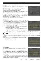
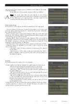
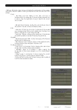
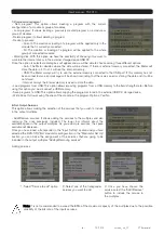
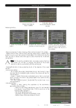
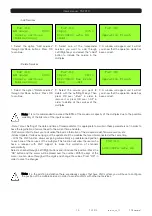
- Settings: This option allows saving and loading the configuration of the module, 
carrying out firmware update or making an adjustment of the time and date of the 
module. 
 - 

Clock: 

- Set Date and time: Setting of the date and time of 
transmodulator. It is appropriate to maintain these parameters set 
in order to have the registration of errors linked to the current 
time and date. 
 
 
- Set date/time all devices: Loading the current date and time of 
the module in the rest of interconnected modules. 

 - 

Alias: 

- Write alias: It allows you to assign a name/alias to the module 
you are programming. Option only available when the Alias Auto 
option is configures as “none” (manual mode). 
- Auto Alias: It allows configuring the name/alias of the modules 
automatically. Options: Channel, Frequency, Service, None. 

 - 

Upgrade: 

- Send Firmware from USB:  It allows carrying out the firmware 
update from the USB device.  
- Send firmware to all:  It allows carrying out the update of all the 


modules that are interconnected at the same time. 


- Configure all devices: 

- Input values to all devices: It allows copying the current input 
configuration in all the interconnected modules. 
- Modulator values to all devices: It allows copying the 
configuration of the current modulator in all the interconnected 
modules. 
- Output values to all devices: It allows copying the current 
output configuration in all the interconnected modules.


- Factory default to all devices: It allows making values by default 
to all the interconnected modules. 


Summary of Contents for TSF 310

Page 1: ...TSF 310 USER S MANUAL...

Page 2: ......

Page 3: ...changes of temperature 8 Never open the device by yourself due to electric risk In case of problems go always to qualified technicians 9 Never under no circumstances open the device when connected to...

Page 4: ...f the module 4 LNC IN To connect to the LNC or to the LOOP OUT output of the previous module 5 LOOP OUT To connect to the ANT IN input of the next module 6 RS 232 Ethernet connector to cascade modules...

Page 5: ...t parameters 1 4 Programming TSF 310 has two ethernet connectors In order to make the programming of the module you have to connect the corresponding programmer to PRO 201 connector You can make the p...

Page 6: ...ption through the key 8 of your field strength meter and to select the Transmodulator Prog option Then it will proceed to recognize the module and to show the main menu In the Transmodulator Prog are...

Page 7: ...ff In Manual mode Off the value of the Symbol Rate should be fixed by the user based on the provider s information In Automatic mode On the meter will automatically identify the SR when a Satellite ca...

Page 8: ...Hz Level Regulation of the output level of the modulated signal Options 0 15dB Calibration Allows the realization of two tests in order to verify the correct running of the device Deactivate output It...

Page 9: ...the Alias Auto option is configures as none manual mode Auto Alias It allows configuring the name alias of the modules automatically Options Channel Frequency Service None Upgrade Send Firmware from U...

Page 10: ...lways the internal memory is used to store the data Load programs from USB This option allows importing programs from a USB memory to the field strength meter Before using this option you must connect...

Page 11: ...ve to configure the position of the module services in order to avoid conflicts with other net services Bandwidth limitation It allows selecting the of the capacity of the output channel Auto service...

Page 12: ...he PRO 201 programmer it will proceed to recognize the module and to show the main menu In the main menu are shown the different options for configuring the transmodulator We have to use the Up and Do...

Page 13: ...allow configuring the DVB T DVB H modulator of the device Modulation Output modulation format QPSK 4 QAM 16 QAM 64 QAM Invert Spectrum inversion Activate or deactivate the spectrum reverse in the mod...

Page 14: ...n concerning the transmodulator is given Read log It allows reading the registered events in the module 1 Select the option Read LOG file through Up Down buttons Press OK to continue 2 Press OK again...

Page 15: ...he registration of errors linked to the current time and date SW version info It allows you to visualize the basic information of the module model firmware version etc Global Update It allows carrying...

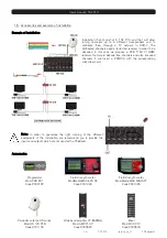
Page 16: ...eceiver that would decode free channels and also encoded channels if we insert a PCMCIA with the corresponding subscriber card Note In order to guarantee the right running of the different equipments...

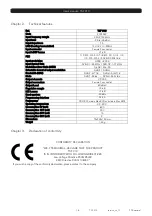
Page 17: ...ndwidth MHz DVB T 6 7 8 DVB H 5 6 7 8 Mode DVB T 2k 8k DVB H 2k 4k 8k Output channels C2 C69 Output connectors Female F connector Output Level 80 dBuV Regulation margin 15 dB MIX Losses 1 dB Band spur...

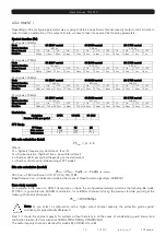
Page 18: ...1 32 1 4 1 8 1 16 1 32 1 4 1 8 1 16 1 32 Duration 358 4us 179 2us 89 6us 44 8us 179 2us 89 6us 44 8us 22 4us 89 6us 44 8us 22 4us 11 2us Modulation Modulation QPSK 16 QAM 64 QAM Number of bits per sym...

Page 19: ...9 353 20 491 21 112 3 4 19 595 21 772 23 053 23 751 5 6 21 772 24 191 25 614 26 39 64 QAM 7 8 22 861 25 401 26 895 27 71 Useful channel capacity 6 MHz Guad Interval Modulation FEC codification 1 4 1 8...

Page 20: ...0 39 05 22 90 97 48 fte fte it www ftemaximal com PORTUGAL Rua Jos Carlos Ary dos Santos A das Lebres Loures 2670 791 Santo Ant o do Tojal Tel 00 351 219 83 87 00 Fax 00 351 219 83 87 09 ftemaximal ft...

Reviews: