700-SDI-RADAR-300W-Man Rev 2 30 May 2022
13
/39
Part# 21370
Table 4-2: Request Example
Name
Content
Detail
Address
0X01
Slave address(Sensor id)
Function
0X03
Read slave info
Data start Addr
0X00
The address of the first register to read (HIGH)
0X00
The address of the first register to read (LOW) – Sensor ID
reg
Data of regs
0X00
High
0X01
Low (read only 1 register)
CRC16
0X84
CRC Low
0X0A
CRC High
Table 4-3: Slave (sensor) Response Format
Name
Address Function
Byte
count
Data
CRC16
Length
1 byte
1 byte
1 byte
2 bytes (H.L.)
2 bytes (L.H.)
Example
0X01
0X03
0X02
0X00
0X01
0X79
0X84
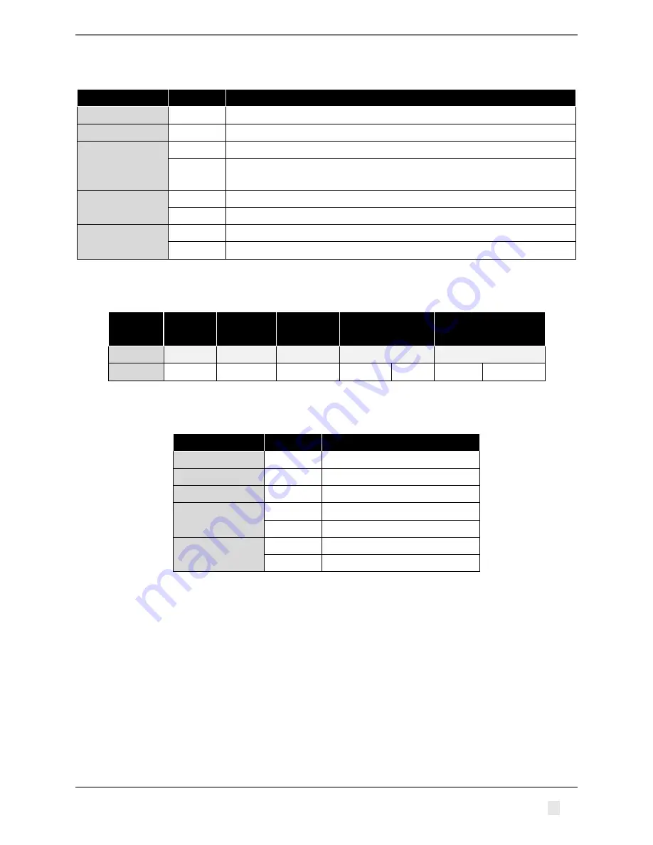
Table 4-4: Response Example
Name
Content
Detail
Address
0X01
Slave address (Sensor ID)
Function
0X03
Read slave info
Data length
0X02
Data length is 2 bytes
Data
0X00
Data high byte
0X01
Data low byte, means ID is 1
CRC16
0X84
CRC Low
0X0A
CRC High
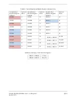
Table 4-5 defines the data returned by the unit when the master requests register read. Table 4-6
defines how to write the device configuration. Rows highlighted in blue denote the important values
measured by the sensor. Rows highlighted in red denote operating parameters that could be
changed in the field.

